PHYS S-12 : Dan's Documentation
2D Design and Modeling
Fusion 360 Modeling
The assignment was to model three objects and put them in an assembly using Fusion 360. I started off by creating a folder where I would store all my components. Each component had its own separate file. Then I measured the dimensions of each component with a caliiper, storing them as parameters. Here is a screenshot of the parameters for my bearing:

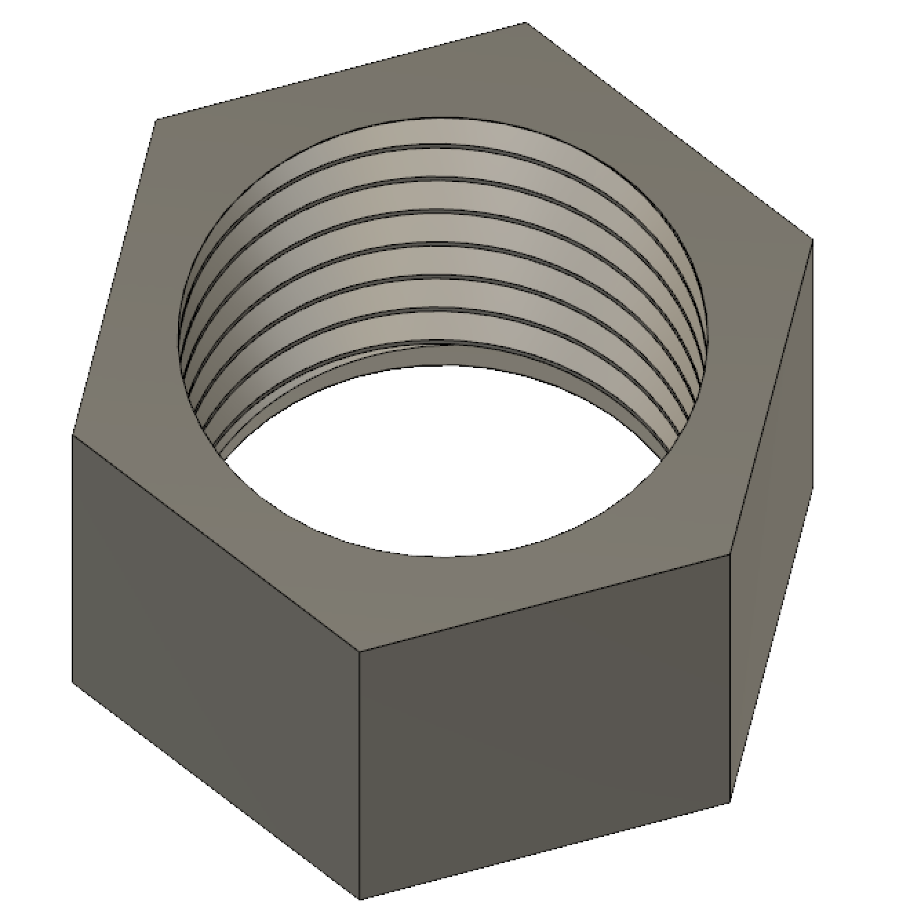
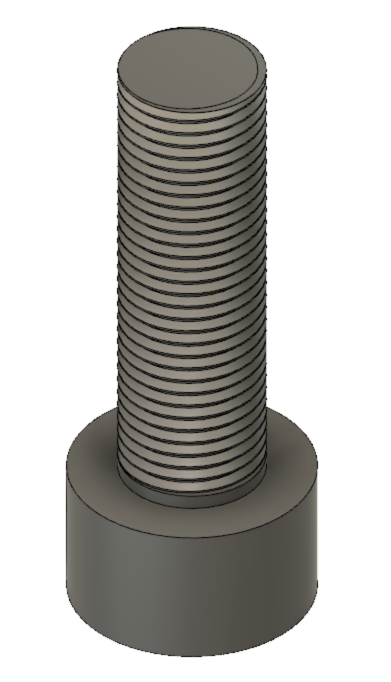
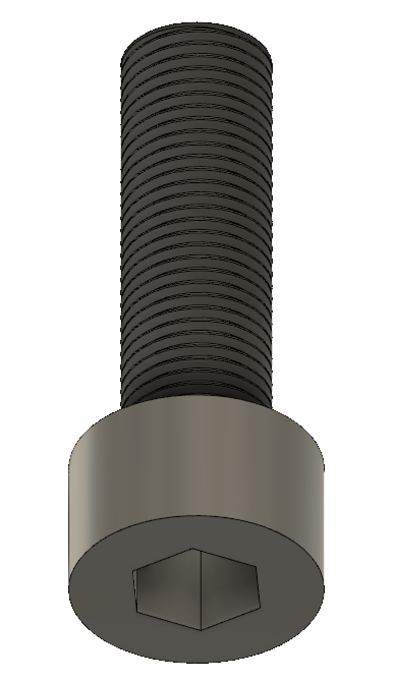
After I measured my parameters, I sketched the basic geometry of each component and extruded them into 3D. I used threading for the nut and screw, and I used joints for the bearing (including decal for aesthetics)
Finally, I combined all three components into an assembly. I used "move" --> "point to point" to easily align the parts.
I loved this Fusion360 exercise because it introduced me to the wonderful world of 2D Modeling. Below are a few of the tips and tricks that I picked up while doing this assignment.
General Modeling Tips
- After seeing the nonfunctional details of the bearings, I realized that I don't need to measure additional details that won't affect the application of the product.
- Parameters allow your design to be fluid and forgiving.
- The backside of the caliper can be used to measure the insides of components. I used this to measure the inner diameters of the bearing and the nut.
- During assembly, different components can be combined easily using : "move" → "point to point".
Threading Tips
- Threading can be done on any cylindrical surface.
- The "modeled" option forces the computer to render the threads more clearly. However, It could become computationally heavy when modeling multiple screws.
- I need to create a small offset (0.01 mm) for the threads so that the nut's opening remains a circle.
- I need to measure the pitch of the threads.
Joints
- The "Joint" option moves the components so that they connect together.
- By selecting two components, I can then choose the way in which they move together.
- I chose "revolute", which makes the two parts of my joint spin together.
- After the joint is created, I could freely spin one part of it by grounding the other component.
Decal
- I used decal to put two "stickers" of my dog, Annie, onto the bearing so that I can clearly see its spinning motion.
- I had to switch to "rendering", and then choose the "decal" option. Once there, I was able to put any image I wanted onto a face that I chose.