PHYS S-12 : Dan's Documentation
Rapid Prototyping
Contents
This documentation is quite long, so please feel free to click on the links below and skip around:
- Introduction
- Rotational Motion
- Sketch
- Assembly
- Trial and Error
- Tuning Parameters
- Prototype #1
- Steering
- Prototype #2
- Improving the Steering
- Prototype #3
- Reflection
Plane Rudder
My preliminary final project idea was to build an RC plane. One of the most important parts of a plane is its rudder, so I decided to make a rapid prototype to test its feasibility.
Rotational Motion
A plane's rudder moves in an oscillating motion, but first, I needed to achieve the most rudimentary type of motion: rotational motion. To achieve this, I used the motor circuit we build during class on Thursday. It is an N2O DC motor controlled by an Arduino Metro Express through a L9110 motor driver.
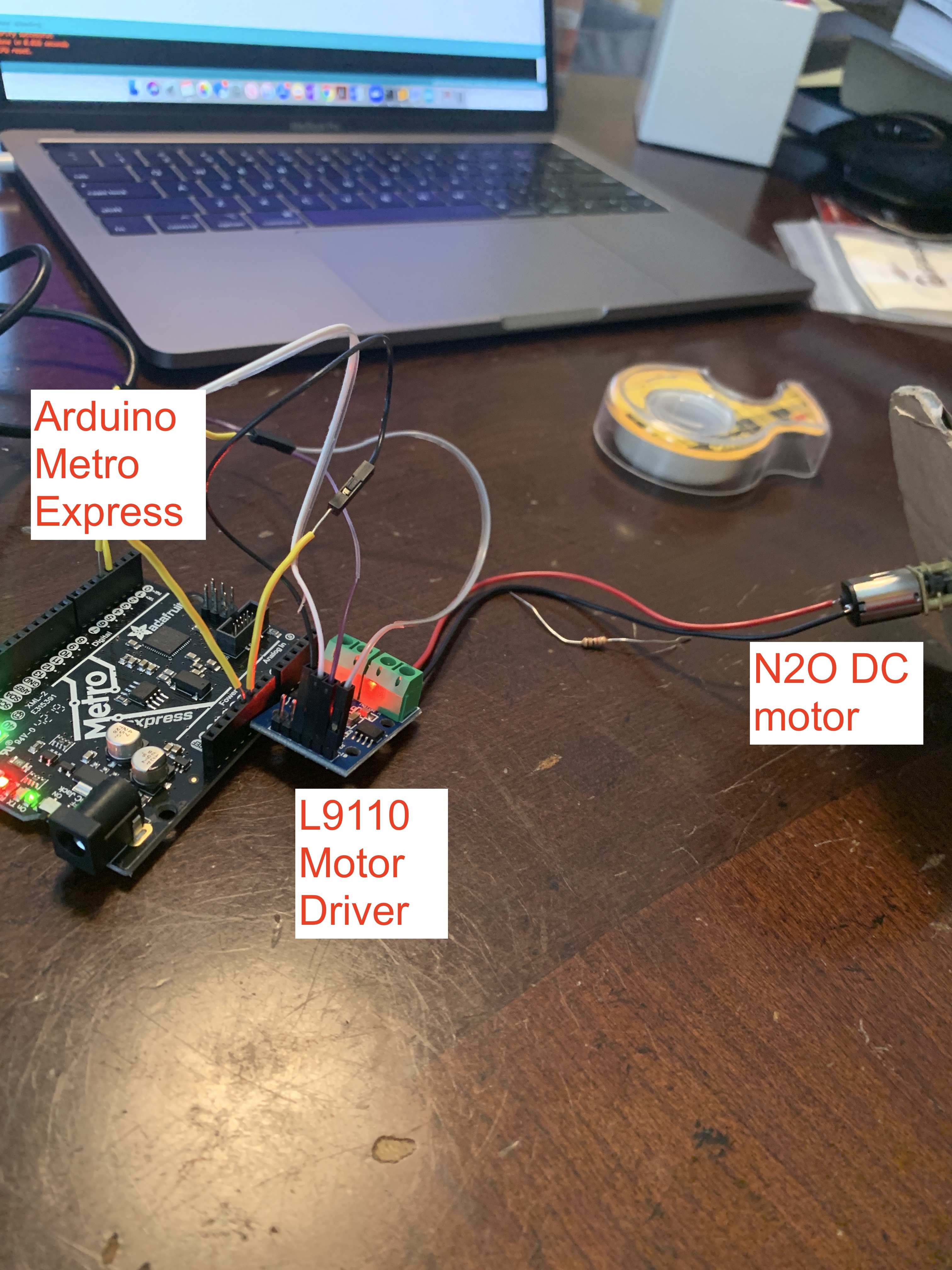
The Arduino code used to run the motor simply sends two analog signals to the motor driver indefinitely, which then analyzes the signals and controls the motor accordingly.
const int A1A = 3;  // define pin 3 for A-1A
const int A1B = 4;  // define pin 4 for A-1B

void setup() {
  pinMode(A1A, OUTPUT); // specify these pins as outputs
  pinMode(A1B, OUTPUT);
}

void loop() {
  motorA('R', 5000, 200); // time doesn't really matter since it will loop forever
}


/*
 * This is a custom function to drive Motor A
 * inputs: direction (L/R), duration (int), speed (int between 0 and 255)
 * outputs: motor control
 */
void motorA(char d, int t, int s) {
  if(d =='R'){
    analogWrite(A1A, 0);
    analogWrite(A1B, s);
  } else if (d =='L'){
    analogWrite(A1A, s);
    analogWrite(A1B, 0);
  }

  delay(t); // allow motor to run for specified time

  digitalWrite(A1A, LOW); // turn motor OFF
  digitalWrite(A1B, LOW);
}
Sketch
Now, I needed a way to convert that rotational motion from my motor into an oscillating motion. Turns out it can be done using a positive-drive oscillating crank. I drew a sketch of it below.
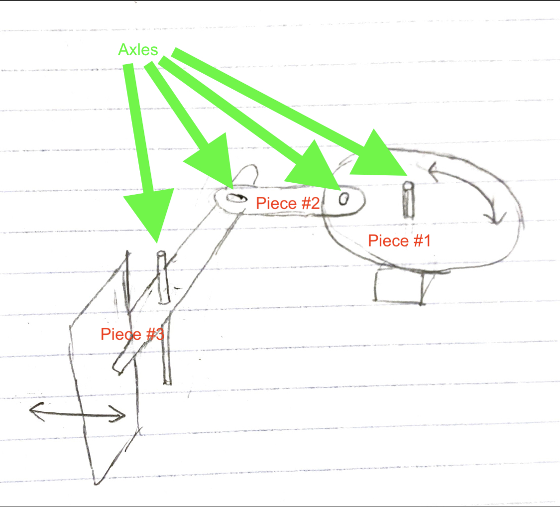
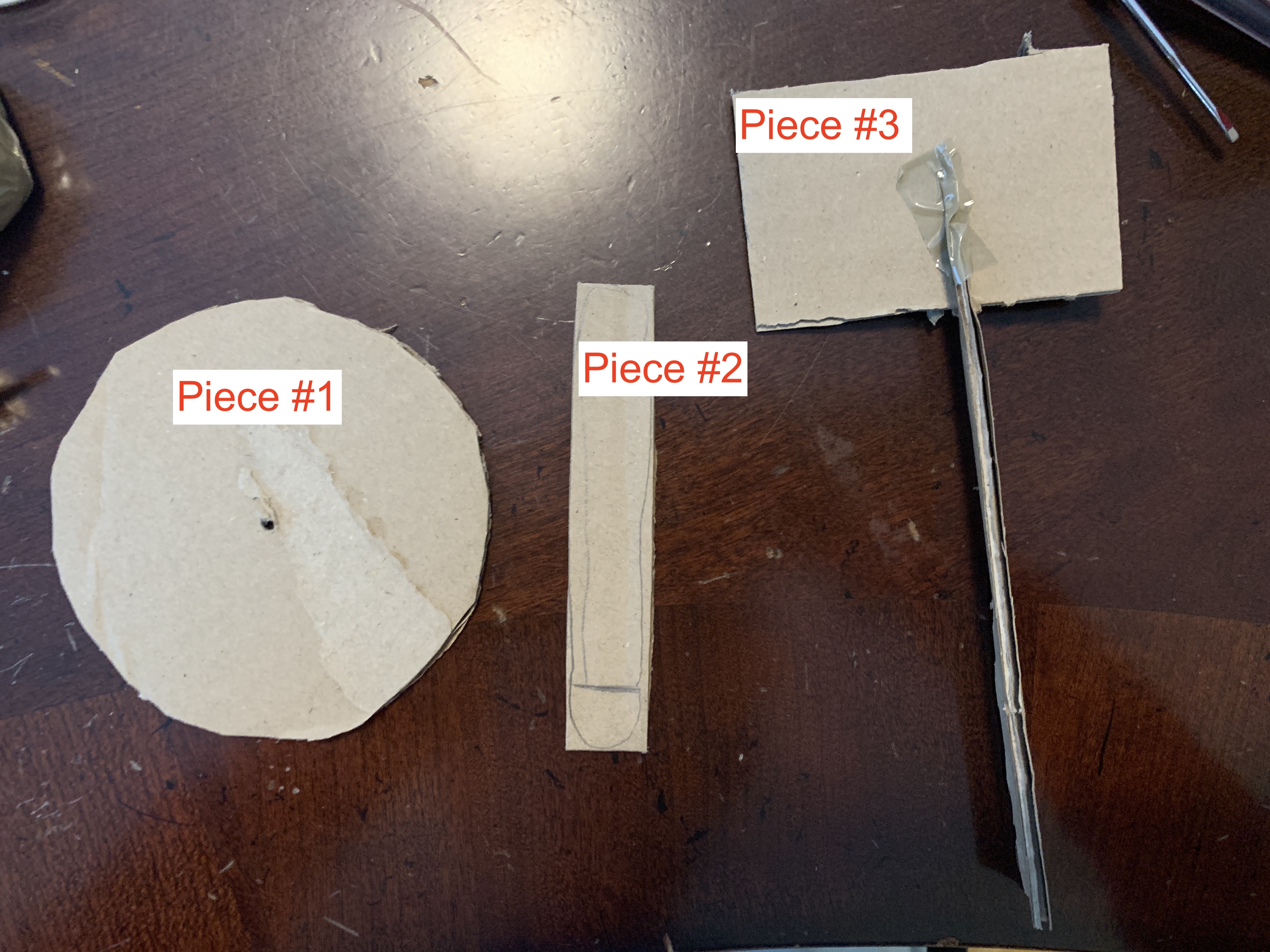
The pieces were to be mounted on a foam board, all the flat surfaces were to be made out of cardboard, and the axles (exluding the motor axle) were intended to be straightened paper clips. I quickly cut these pieces out with a pair of scissors
Assembly
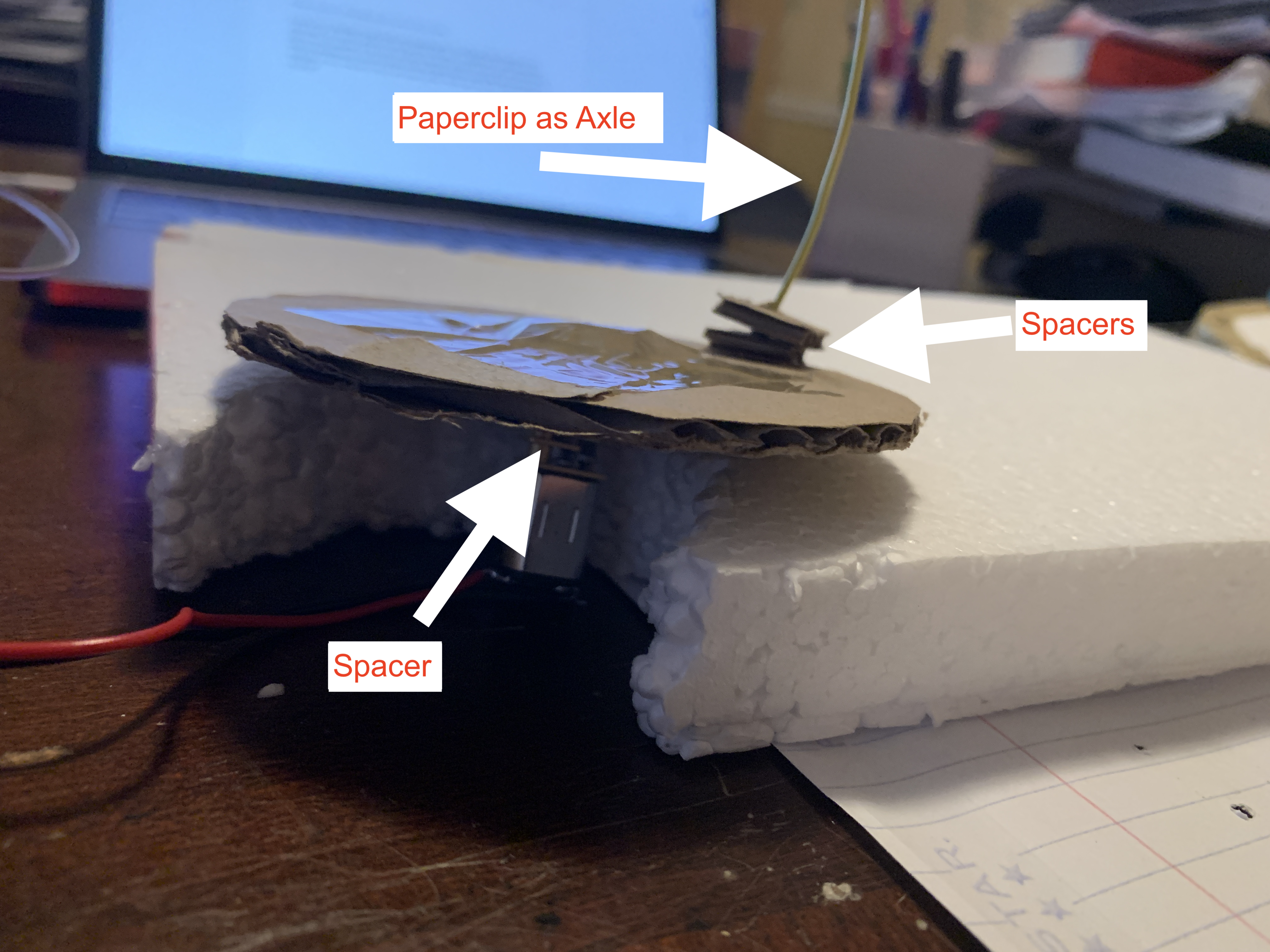
It was time to assemble these pieces into separate parts. The first part was the motor + piece #1. As I tried to attach piece #1 (circle piece) to the motor, I realized that I needed spacers so that my circle stays flat on the motor and so that piece #2 doesn't interact with the motor's axle. With the spacers put in, piece #1 now fits snugly onto the motor axle, and I secured it with duct tape. I then ductaped the whole contraption into a foam board, which I will be using as the fundation of the prototype.
Moving on to the second part, I first combined pieces #2 and #3 with a paperclip. Then I mounted the axle of piece #3 and added two spacers (in order to compensate for how high up piece #1 was). After that, I simply lowered the assembled pieces onto the axles.
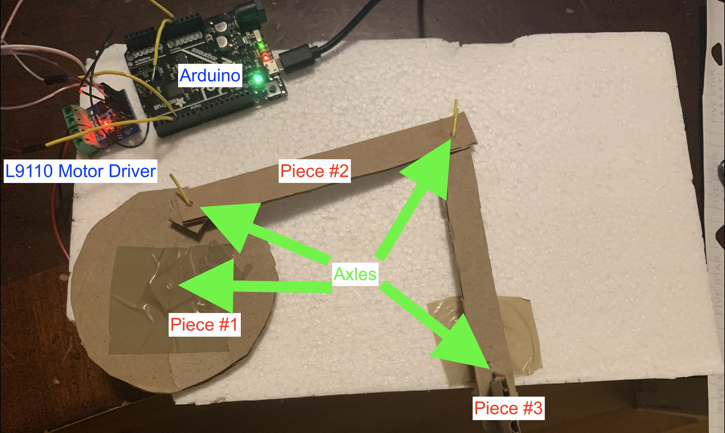
Trial and Error
The prototype looked complete, but it was far from over. The next step was experimentation. I needed to test the contraption and fix any problems that arise.
The first time I ran the motor, piece #1 wouldn't spin at all. The motor's axle was spinning, but the cardboard couldn't cling on to the axle. I decided to use Elmer's glue (the only one I had availble) to stick together the axle and the cardboard. I set it to dry while I took a break. After a lengthy wait, it worked!
However, the rudder quickly stopped turning again. This time the cardboard was caught on the styrofoam. In order to fix this, I disassembled the axles and added more spacers to elevate the cardboard pieces off of the foam board.
Tuning Parameters
All that was left to do was to fine tune the parameters by testing. I first adjusted the spacings of the axles to guarantee that my rudder had a full range of motion. Then I moved on to the motor speed. I adjusted the voltage going to the motor using analog output and PWM. Now the rudder can correctly move around!
Prototype #1
The obvious shortcomings of this prototype were that It couldn't be controlled (therefore useless as a means of steering) and it was not structurally sound. The second problem was harder to fix since I didn't have anything other than weak Elmer's glue and cardboard at home. This could be dealt with in future designs by using Metal Epoxy and 3D-Printed parts. The first issue, however, was not nearly as hard to fix.
Adding Steering
I started fixing the steering problem by adding a potentiometer. I planned on adjusting the power of the motor based on how far its knob turned and the direction based on which way its knob turned. If the potentiometer was in the middle, then the motor would stop. I quickly built a potentiometer circuit modeled after the following design I created a few days ago.
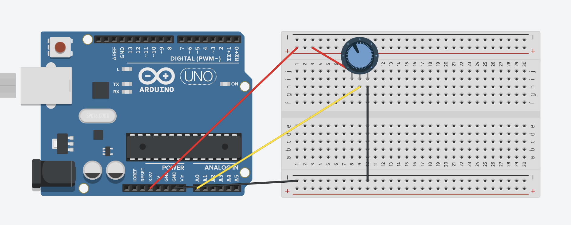
Now armed with a potentiometer, all I had to do was convert its analog reading, 0 - 1023, into my motor's power level, 0 - 255. I did this using the following code inside the main loop.
Edit: I am writing this short note after attending the lab on monday. Sadly, I wrote the following code before we learned about connecting potentiometers to motors in the Lab. Therefore, you won't see me using convenient functions like map() here. I believe, however, that my clunckier code does achieve the same functionality as what we talked about in class.
int analogNum = analogRead(analogInputPin);
analogNum = analogNum / 100 - 5; // divide by 100 and subtract 5 to reduce the input to a -5 to 5 scale.
                                 // When divided by 102.3, the numbers would flicker at the ends, so I decided to go with 100.
analogNum *= (255/5); // now scale the small numbers up to 255 (or -255).
The main goal here was to combine the potentiometer's 1023 parts into just 10 total parts. This is important mostly because it would be nearly impossible to turn to the exact middle of 1023 in order to stop the motor from spinning. But when the knob only corresponds to 10 total numbers, there would be a comfortably wide middle section of the potentiometer's knob that lets me easily stop the motor. Secondly, this would give me more control over the motor as it won't sporadically change power at the slightest turn of the knob.
The 10 parts scale from -255 to 255 because 0 to 255 is the range of power a motor receives. The sign indicates the direction of the motor. Positive is Left, Negative is Right. The numbers are implemented in the following way.
if (analogNum > 0) { // this means potentiometer is turned to the left, so turn left accordingly
    motorA('L', analogNum); // turns motor left with analogNum as power
}
else if (analogNum < 0) { // turns right
    motorA('R', analogNum * -1); // needs to make the analogNum postive first.
                                 // turns motor right with analogNum as power
}
else { // stops the motors if analog reading = 0
    analogWrite(A1A, 0);
    analogWrite(A1B, 0);
}
A1A and A1B are predefined analog output pins connected to the L9110 motor drive. The complete code can be downloaded here .
Prototype #2
This type of steering is by no means ideal. I'd want the rudder's angle to correspond to how much I turn my potentiometer. However, this is unrealistic for a DC motor as it won't rotate the same amount when following the same exact commands.
Improving the steering
After doing some research and asking for help, I realized that I needed to use a Servo motor, which would give me precise control over its angular position. It is quite a simple motor to use. It has three wires: power, ground, and signal. And it can be controlled using an analog signal between 0 and 180, which corresponds to degrees.
My job was made even easier when I stumbled across a demo code which links a potentiometer to a servo. I found it on the Arduino's official website while looking up documentation for the Servo library.
// The following code came from the official arduino website: https://www.arduino.cc/en/Tutorial/Knob
#include

Servo myservo;  // create servo object to control a servo

int potpin = 0;  // analog pin used to connect the potentiometer
int val;    // variable to read the value from the analog pin

void setup() {
  myservo.attach(9);  // attaches the servo on pin 9 to the servo object
}

void loop() {
  val = analogRead(potpin);            // reads the value of the potentiometer (value between 0 and 1023)
  val = map(val, 0, 1023, 0, 180);     // scale it to use it with the servo (value between 0 and 180)
  myservo.write(val);                  // sets the servo position according to the scaled value
  delay(15);                           // waits for the servo to get there
}
I drew up a quick layout of the servo motor. I wasn't able to do this for the DC motor because tinkercad doesn't have the L9110 motor driver.
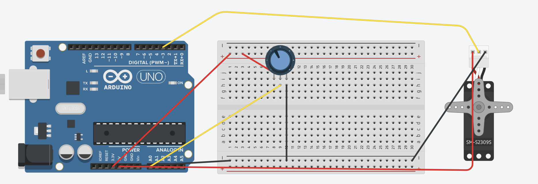
All that was left to do was to build this layout and connect the motor to my crank system, which I easily did by ductaping the motor's plastic mount (the white "horn") to piece #1 (the circle piece).
Prototype #3
I fixed the steering problem! Now the potentiometer actually controls the angle of the rudder, not just the power of the motor. This prototype is different from the previous two as I replaced the DC motor and its motor driver with a servo motor. Furthermore, my crank system is short one axle since I was able to attach the servo motor without one.
Reflection
This prototype helped me gain a better understanding of oscillatory motion and how to convert to it. It also made me assess my available materials, so now I know what supplies to buy. Furthermore, I learned how to use a servo motor. It seems very useful since I can precisely control its angular position. It was also very fun to come up with creative ways to replace standard material (such as a paperclip for an axle).
Even if I don't end up building a plane for my final project, I can still find a lot of uses for this oscillating motion. For example, I could replace the rudder with a propeller, which would allow me to control a hot air balloon.