PHYS S-12 : Dan's Documentation
Programmable Electronics
Today in class we learned about the programming language behind the Arduino. Since I have already taken AP Computer Science and was familiar with coding an Arduino, I decided to skip ahead a bit and play around with the Huzzah board.
The Huzzah board is perfect for my final project: a hot air balloon. This is because it is light weight and has long range communication capabilities. From now on, I've decided to switch from my Metro Express to using this board exclusively. I'd like to get comfortable with using it before I start my final project.
Assignment: Conditionals and Loops
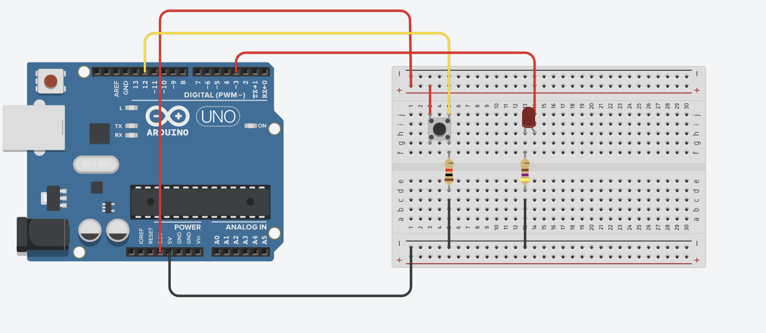
To fulfill the assignment, I simply created an LED that fades for 2.5 seconds when a button is pushed. Here is the layout. Please note that I used a Huzzah board for this, so the pins are not exactly right.
The main challenge, however, was learning to use the Huzzah board. The first problem I had was figuring out a way to send analog signals.
After getting countless error messages from trying to use analogWrite(), I figured that the function wasn't written for the Huzzah Esp32. I searched online for the esp32 documentation, and I found two ways to send analog signals.
1. DAC pins
DAC stands for Digital to Analog Converter, and there were two pins set for this purpose, DAC1 and DAC2. The range of value is 8-bit, meaning from 0 to 255. I am not exactly sure how the digital signal is converted into analog output.
Anyways, all I had to do was import the DAC library, #include <driver/dac.h>, set up the pin by using dac_output_enable(DAC_CHANNEL_2), and then send the analog signal with dac_output_voltage(DAC_CHANNEL_2, variable_signal_strength). The code is basically the same as the one below, which is why I haven't included it on my website. Here it is if you want to download it.
2. LEDC(PWM) pins
There are 16 LEDC (LED control) pins that uses PWM with an 8-bit range. Instead of using the LEDC library, however, I installed the analogWrite.h library. This is simply a wrapper for the LEDC library, which lets me use conventional function names such as analogWrite().
#include <Arduino.h>
#include <analogWrite.h>

const int inputPin = 12;
const int analogPin = DAC2;
int sensorVal = 1;

void setup() {
  pinMode(inputPin, INPUT);
}

void loop() {

  int prevSensorVal = sensorVal; // store the previous value of the pushbotton
  sensorVal = digitalRead(inputPin); //read the pushbutton value into a variable


  if (sensorVal > prevSensorVal) { // if button is pressed (bascially if it switches from off to on)
      for (int i = 255; i >= 0; i--) { // iterate 255 times, each time for 10 milliseconds. Total of 2.5 seconds.
      analogWrite(analogPin, i);
      delay(10);
      }
    }
  else { // turn off when button is not pressed
      analogWrite(analogPin, 0);
  }
  delay(20);
  // The button is really jittery, so the delay is to prevent the board from picking up its random signals.
}
The code and circuit worked out great! Here is the video showcasing the design.
DAC pin Errors
Something really strange caught my eyes. When I used the LEDC pins, the LED stayed bright for much longer than when I used the DAC pins. I ran some test code and confirmed that my for loop wasn't at fault. This could only mean that the LED stops lighting up for a lot of the lower/middle values of the DAC pins.
After some experimentation with the DAC pins, I found that the LED pin only lit up between a signal of 160 to 255. I measured the voltage (using a multimeter) across the LED pin with an output signal of 160 and received 2.07V. This measurement agrees with the theoretical math (3.3V * 160/255 = 2.07V), which means that the DAC pin is actually sending out the correct amount of voltage. The only other possible explanation was the current. I measured the current between the DAC pin and the LED, and it turned out to be only 1μA.
I did the same measurements for the LEDC pins which sent PWM signals, and I made sure that the pin was sending out the correct amount of voltage. I then repeated the experiment with value set at 255. Here is a clear layout of each set of data.
DAC at 160: 2.07V, 1μA (no light)
DAC at 255: 3.14V, 1.29mA (light)
PWM at 160: 2.03V, 805μA (light)
PWM at 255: 3.24V, 1.45mA (light)
As you can see from the data above, there's not much of a difference in voltage between the two kinds of outputs. The answer was in the current. At full power (255), the current between the two were in the same ball park. However, at value = 160, the current of the analog signal sent by the DAC dropped down to almost nothing while the digital signal sent using PWM had a current of 806μA. Sadly, I couldn't use Ohms law to help me here since the circuit involves a diode.
My hypothesis is that the DAC pins are either not designed for output or that the manufacturing of the board was faulty. This is very interesting, and I'd like to do more research into this in the future.
Final Project and 3D Modeling
Part of our assignment was to start thinking about our final project and also to design a simple 3D model. I have created a separate page for anything related to my final project, and you will find my assignment there.