PHYS S-12 : Dan's Documentation
Final Project
Final Project Page
Please click on the above link to see my final project presentation. This page is an extensive documentation of my process and contains all the files I used.
Contents
This documentation will is quite long, so please feel free to click on the links below and skip around:
- 7/7: Getting Started
- 7/9: 3D Design and Printing
- 7/14: Sensor Brainstorming
- 7/16: Testing
- 7/21: Networking
- 7/29: Soldering
- 7/31: Basket
- 8/1: Envelope and Testing
- 8/3: Implementing Sensors
- 8/4: Web Interface and Data Visualization
- 8/5: Installing Electronics
- 8/6: Results
7/7
Dr. Hart suggested that I should adapt my RC plane idea into an RC hot air balloon, and I honestly think it's even cooler than my original plan. As a bonus, it will also be easier to execute, given the much more forgiving aerodynamics behind a hot air balloon.
After a few very helpful discussions with Nathan, Victoria, and Dr. Hart, I identified the challenges I'm facing and how I should approach them. My biggest problem would be providing enough buoyancy force for my load. Below are a list of materials that I've come up with to decrease my weight and increase my buoyancy as much as possible.
- Power Source: Lipo 3V battery for the microcontroller
- Basket: Laser Cut 1/16 inch plywood (Drawback is it could be Flammable)
- Additional Bouancy Source: Helium filled mylar balloons.
My thought was that I could balance the load and helium balloons precisely so that the hot air balloon is barely floating. Then I would produce hot air with light weight candles in order to lift off. I could control the height of the ballon by covering up the flames with a piece of aluminum foil controlled by a servo motor.
I'd like to learn and calculate the weight of my load. Then use that and calculate the amount of helium I would need to buy. However, in order to do these calculations, I needed to learn the physics behind a hot air balloon.
Physics
The most important factors when considering a hot air balloon is its center of mass, centroid, weight, volume and buoyancy force.
This website explains buoyancy very clearly: "For a hot air balloon, the upward buoyant force acting on it is equal to the weight (or mass) of the cooler surrounding air displaced by the hot air balloon. And for lift to be generated, this buoyant force must exceed the weight of the heated air, plus the weight of the envelope, plus the weight of the gondola, plus the weight of equipments on board."
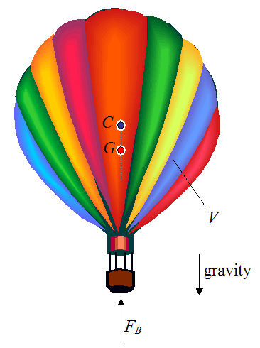
One more important thing to note is that the centroid(C) of the ballon must be directly above its center of mass(G) in order for the ballon to keep its balance.
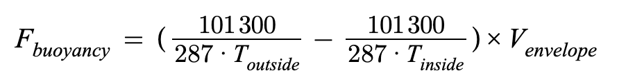
Now, to calculate the buoyancy force, I first needed to calculate the density of the air using the Ideal gas law: P = ρRT. (The following equations are derived from this website
- (P) Normal atmospheric pressure is approximately 101,300 Pa.
- (R) The gas constant for dry air is 287 Joules/kg.
- (T) The heat of the air inside the envelop is still unknown, I will have to conduct experiments with my hot air source.
Substituting all three values, I get ρ = 2.83 * 10-3T kg/m3. This is the density of the heated air, whereas normal dry air is around 1.2 kg/m3.
The net buoyant force is defined here as the difference in density between the surrounding air and the heated air (1.2−0.946), multiplied by the envelope volume (m3). Thus,
FB, net = (1.2 - 2.83 * 10-3T)×Venvelope kg
Writing this on 7/16: I made some mistakes in this formula, please go here to see the new version.
For now, I have no concrete data on the Temperature or the Volume. However, let us assume that I use a 210 cm * 160 cm mylar blanket as the envelop. By approximating it as a sephere, I can convert the 3.36 m2 surface area into a 0.58 m3 volume. Let's also assume that the temperature is raised by 60 degrees kelvin. That would give me…
FB, net = 600 grams (rounded with sig figs)
Load Weight
600 grams of buoyancy force doesn't sound like a lot to work with, however, that is not the case when we examine the weight of our components
- Servo Motor: 9 grams
- Huzzah: 8.4g
- 1/16 Plywood: Unknown, but let's assume around 100g.
- Mylar envelop: 60g
- Aluminum foil: Barely anything
- Wax: Around 28 grams (1 ounce) for five to six hours of burn time
- Wax container: 3D printed, assume around 200g for now
That gives us a total of 405.4 grams of weight. This means the hot air balloon would rise comfortably while still being flexible to variables such as the candle's heat and the envelope's volume.
Revised Plan
After doing these theoretical calculations, I realized that I can make some significant changes to the original balloon.
First of all, there's no longer any need for helium balloons as the buoyancy force that could be generated from my materials is greater than the weight of the load.
Secondly, I've decided on using mylar as the material for my envelope. It is sold in a large surface area, it is super light weight, and it has 90% Heat Retention.
Finally, I've decided on replacing the wax candles with custom wax that I am going to make. I will modify the wax to create as much heat as possible by adding more wicks, using thicker wicks, and mixing flammable liquids into the wax. Because of this, I will need a custom candle holder, which I am about to make as part of Day 5's assignment.
3D Modeling
Time to finally stop planning and get to work! Day 5's assignment, to create a simple 3D model, fits very well into my final project. I will be using this opportunity to create a wax holder.
First, I needed to decide on the volume. Although an average 1 oz candle's burn time is five to six hours, my custom wax will burn far hotter, and therefore have a shorter lifespan. I'll go with 2 ounces (59147 mm3) for now. If I need to change this after I've done some testing, I can always get new material since I live so close to the Harvard Fab Lab. Next, I chose an arbitrary radius for the cylinder: 31.75 mm (1.25 in). However, let's make the thickness 4 mm so that the holder doesn't break. Now the inner radius is 27.75.
V = πr2h
59147 / π27.752 = h
h = 24.45 mm
Now, I'm going to add 10mm to the height to prevent overspill.
h = 34.45 mm
I finished off the design by adding a fillet at the bottom so the wax won't get stuck, chamfering the top for aesthetics, and adding standoffs that will fit snugly into 1/16 inch plywood.
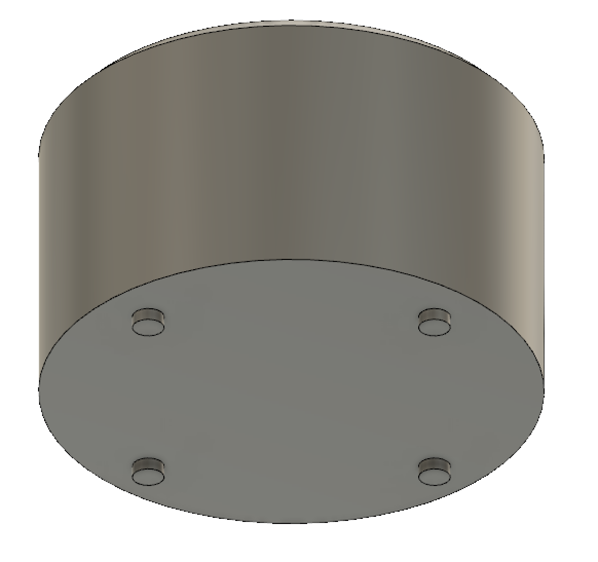
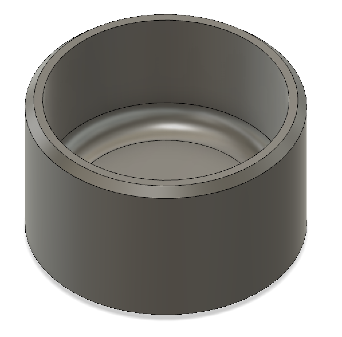
To see the model yourself, go here.
Future Plans
Next time I work on the final project, I want to create a lasercuttable model of my basket. I will also start testing as soon as the materials arrive through Amazon.
7/9
Heat
I've forgotten about a very important factor up until today. Electronics are only functional below a certain temperature. Most Servo Motors and Lipo Batteries can't survive temperatures above around 50 degrees celsius. However, the components should be able to avoid the heat if we place them below the wax holder (hot air rises up, not down). Because of this, there will be some design changes I need to make.
- The basket now needs two compartments stacked on top of each other. One for the fuel (wax) and one for the circuit.
- I'll need to 3D print an extended axle for the servo motor that holds on to the aluminum. This axle will be made out of PLA, which is heat resistant. This will place the motor well below the flames, protecting it from the heat.
- As a last resort, I can always wrap the electronics in thin heat insulators.
Servo Motor
I was worried that the Servo motor wouldn't cooperate with the 3.3V power source of the esp32. Even the product's documentation suggested a minimum operating voltage of 4.8V.
I quickly hooked up the servo to the Huzzah and tried to run a test. However, I was stumped by the fact that the ESP32 didn't support the arduino's servo library. After a quick look online, I found that I could control the servo with the LEDC library. While this worked, I still wanted to use the Arduino's convenient servo library, and my wish was granted when I found its wrapper library for the ESP32 called ESP32Servo.
I also learned that I could set up the servo's pulse width range through myservo.attach(pin, min, max). Using the documentation of the motor I linked above, I found this particular servo's pulse width to be between 900 - 2100μs. Anyways, here we go, finally testing...
It worked! I even put some load on it to make sure it could turn a 3D printed axle. You can download the code here.
3D Design and Printing
Since 7/14 is the deadline for submitting requests for custom materials, I thought it would be best to get started designing them right away. Here's a list of what I need to submit by then:
- 3D printed Servo motor mount.
- 3D printed extended axle that attaches to the servo's white "horn", which holds on to a piece of aluminum. Main purpose is for keeping the motor away from the heat.
- Lasercut Basket with two compartments
Lasercut Basket
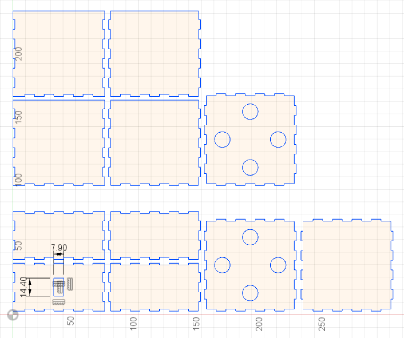
By designing the container first, I will have an easier time modeling everything else afterwards. I first went on MakerCase to get a preliminary design of my box. It's very convenient, and it allowed me to download a DXF file of a box with dimensions of my choosing.
In order to get two compartments in my box, I just needed to build two separate boxes and attach them together. I combined the two DXF files together in Fusion, laying them out side by side.
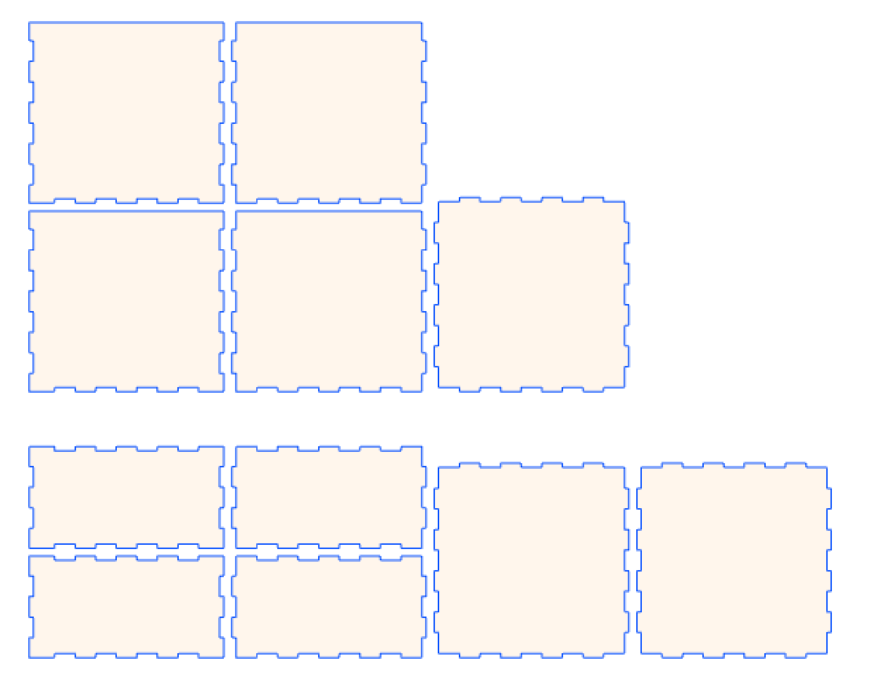
My lower compartment's dimensions are 70 x 70 x 35 (mm) and my upper compartment is 70 x 70 x 66.4 (mm). These measurements will be large enough to fit my load.
Next up, I need to add in an opening for the wiring of the motor and holes for the wax holder's standoffs to fit in. I'm also making sure to add 0.4mm to each opening to give my materials some leeway.
Here is my design for the hot air ballon basket. In the future, I might considering adding in "ventilation" for the candle if my initial tests indicate a need for it.
During this process, I went back and slightly enlarged the standoffs of the wax holder in order to increase its stability. I also increased the height of the standoffs since they'll be going through two layers of plywood.
You can download all the design files here
Edit: I'm writing this on 7/14. Minor redesign: I added openings on all four sides of the bottom compartment to 1) Allow wires to easily reach sensors/motors, and 2) Use the wind to cool down the circuits. I've updated the downloadable files accordingly.
Edit #2: I'm writing this on 7/30, after I've received my basket. The lower compartments didn't align together since the extrusions blocked eachother. I removed the extrusions on two of the bottom boards and added more spacing so that all four bottom boards would fit together. The download files have been updated accordingly.
Motor Axle
After some consideration, I realized that adding a long axle and gears to a single side of the basket would most likely either shift my balloon's center of mass or make it unable to fly at all. For now, I think I'll take on the heat risks for the motor and just attach the aluminum sheet directly to the servo horn.
Motor Mount
Please go here to see my progress.
Downloadable Designs
Here are the two parts I designed today plus the wax holder from 7/7 (with minor modifications).
Laser Cut 1/16 inch Wooden Basket (F3D)
Laser Cut 1/16 inch Wooden Basket (DXF)
Servo Motor Mount (F3D)
Servo Motor Mount (STL)
Candle Holder (F3D)
Candle Holder (STL)
Servo Motor Mount and Candle Holder (Gcode)
7/14
Today I'll just be jotting down some ideas for integrating sensors into my hot air ballon.
- Wind direction sensor with capacitance sensing.
- Need one on each side, 4 in total.
- Likely to be unreliable since it would be homemade.
- Hot air temperature sensor with a thermistor.
- Knowing the temperature can help me control the height of the balloon.
- I've already calibrated the sensor here.
- Velocity and orientation detector with Inertial measurement unit (IMU).
- Knowing the speed, direction, and tilt of the balloon would make it easier to control.
- Detect height with atmospheric pressure sensor.
These sensors all weigh next to nothing, and they can be attached and organized via this tiny breadboard (47mm x 36mm) I found online.
7/16
Before we dive into the testing, I'd just like to mention that I figured out a potential solution for keeping my Servo motor out of the heat. I have paper clips that fit perfectly into the tiny holes in my servo's horn when they're stripped. I can use this to hold up the aluminum and keep the motor safe from the flames.
Molding Wax
My wax was recently delivered by Amazon. Over the weekend, I will make different kinds of wax and record their temperatures.
First, I needed to make the wax. I consulted this guide, and it seemed surprisingly more involved than I had imagined. Nevertheless, I still went ahead and made the candles.
I made 2 types of candles for testing, both with four wicks to increase the flame size.
- 4 oz Soy Wax
- 2 oz Soy Wax mixed with 2 oz 60% Isopropyl Alcochol
I used Soy Wax because it doesn't release fumes that are toxic to the environment. Sadly, it also burns at a lesser temperature than paraffin wax. As for the container, I substituted some glasses for my 3D printed wax holder (currently on the way).
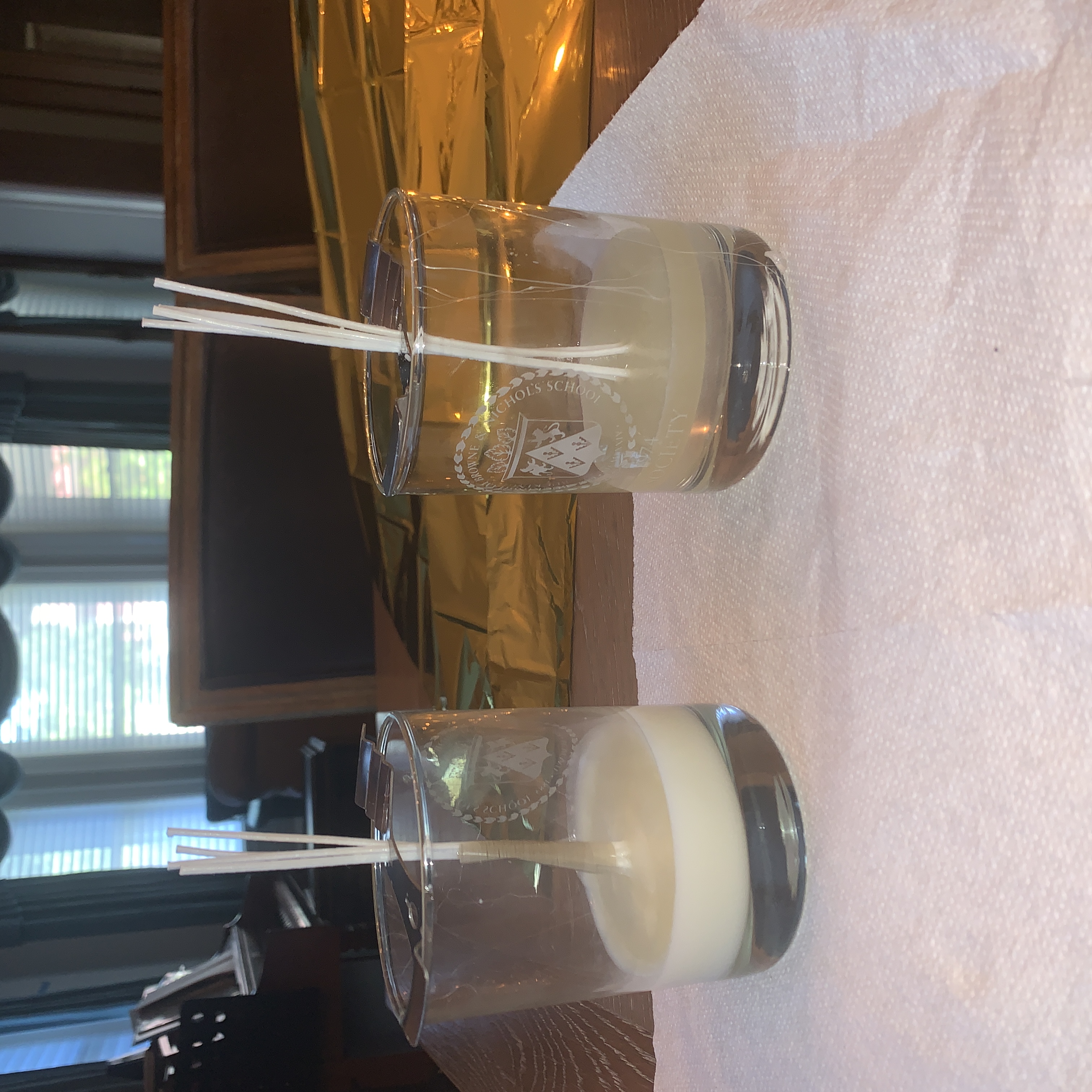
After 4 hours of cooling, which is what the guide recommended, the wax was ready for burning. However, the mix of wax and alcohol did not turn out well. The wax was lighter than the alcohol, so they separated into two different layers. I have yet to find a solution for this, but for now I literally just poured more alcohol on top of the wax, just to see the temperature at which it burns.
Testing Temperature
I taped my mylar blanket to the glasses as a temporary envelope. I quickly rebuilt my thermistor circuit and taped the thermistor to the top of the envelope. I can easily sense temperature with it since I had already calibrated it.
I took my setup outside and got to testing. My envelop for now is simply a rectangle with its corners attached to the container, so that's why it looks off. However, I didn't need to get any more complicated than that for a temperature test.
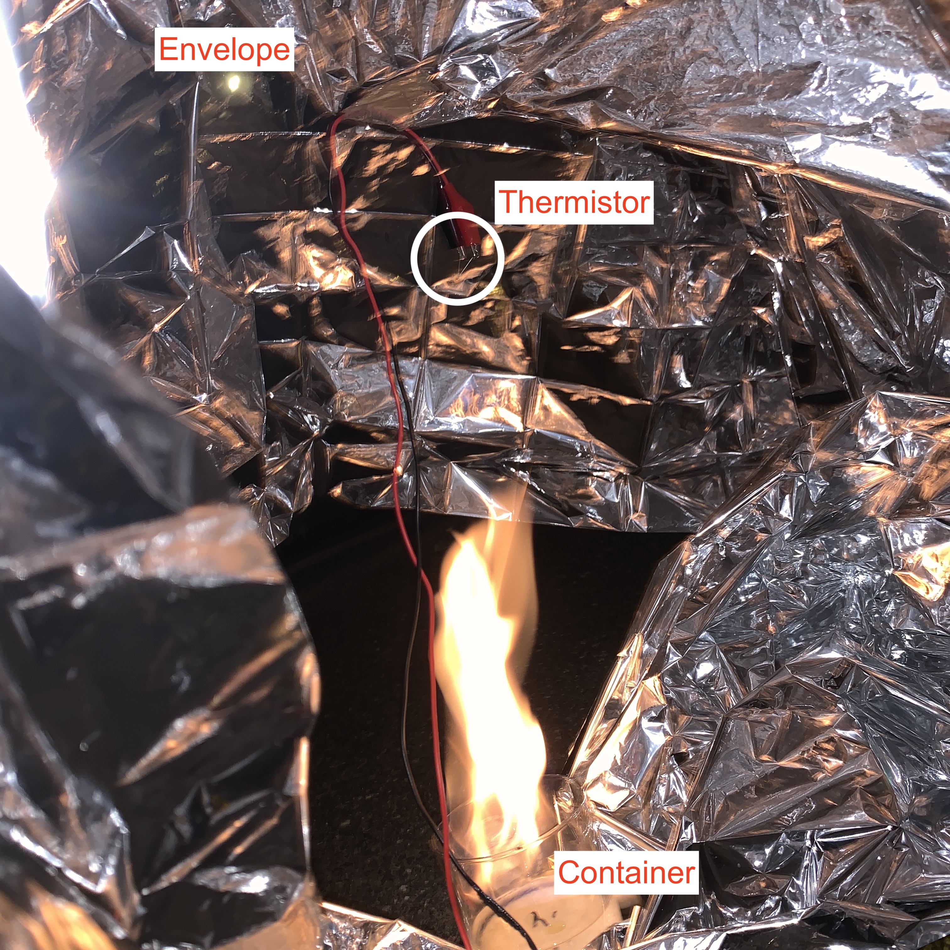
Unfortunately, I had to restart the experiment since a wire in my thermistor circuit accidentally came off. I also witnessed this moth flying into my fire with no regard for his life.
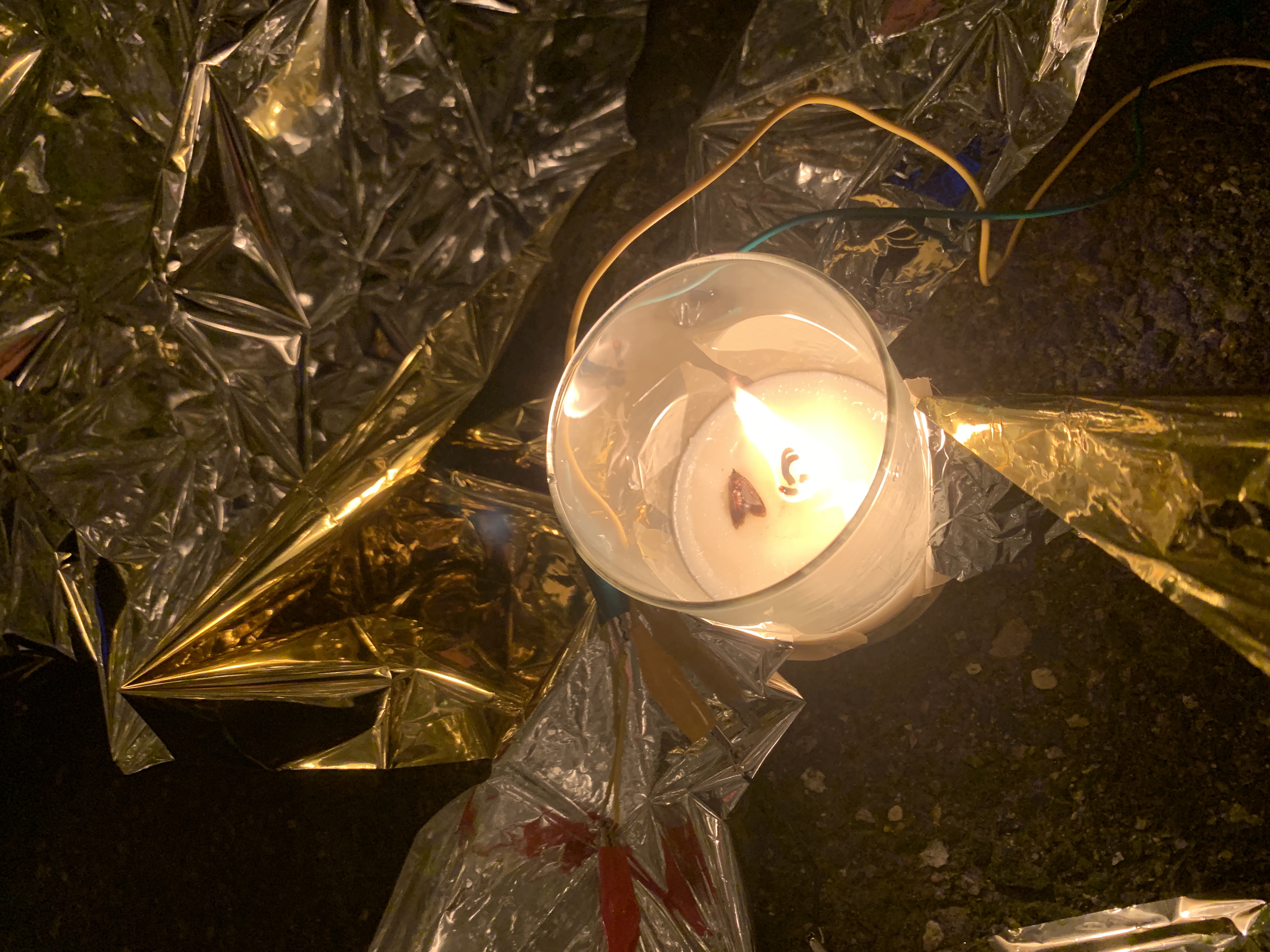
Perhaps I can harness the wind energy that moths generate and use it for steering? I'll have to do some serious research into this later.
Anyways, here are the results of my tests in Celsius.
- Normal Temperature: 28.39
- Soy Wax: 64.78
- 60% Isopropyl Alcochol: 111.11
One thing I'd like to note is that my thermistor isn't great at calculating temperatures above 100 degrees celsius. I am getting an actual thermometer so hopefully I'll be able to know the temperature more accurately.
Calculations
I plan on using the same formula I wrote way back on 7/7. I actually noticed a few mistake that I made back then. My first mistake was that I set a static density for the "outside" air, and my second was an arithmetic error. Here is the corrected formula (resulting units are in kg).
Ideally I want my buoyancy force to be 500 grams so that I have some leeway. I converted my results above into Kelvins, and ran the calculations.
I found that I need a 1.99 m3 envelope to lift 500 grams if I used 60% Isopropyl Alcochol, and 4.44 m3 if I used the soy wax. Obviously, I'll go with the smaller envelope.
My envelope will be made from a cutout of a circle.
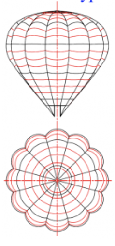
Approximating it as a sphere, the diameter of that circle becomes the circumference of a plane of the sphere. So starting with the volume, which is 1.99 m3, and working backwards, I can get to the radius (0.78 m), and from there calculate the circumference, which is equal to the diameter of the circle cutout (4.9 m).
Conclusions and looking ahead
To summarize, I learned from this weekend's testing that I need a circle with a radius of 2.45 meters in order to make an envelop big enough for my hot air balloon. Use this site to help with construction.
Alternatively, I could use 99% Isopropyl Alcochol, which will surely increase the temperature by a lot more than the 60% did. My house already has some of this, and I'll test it as soon as my thermometer arrives (thermistors can't go above 100 Celsius)
The final option would be to strap on some 36'' helium balloons and use a smaller envelope. I would balance the load weight and the balloon's buoyancy force just right so that I'll be able to control the height with my hot air.
7/21
Today I created a firebase database that communicates with the ESP32. I also created a webpage to interface with the database.
My description will be super brief since my documentation is already here.
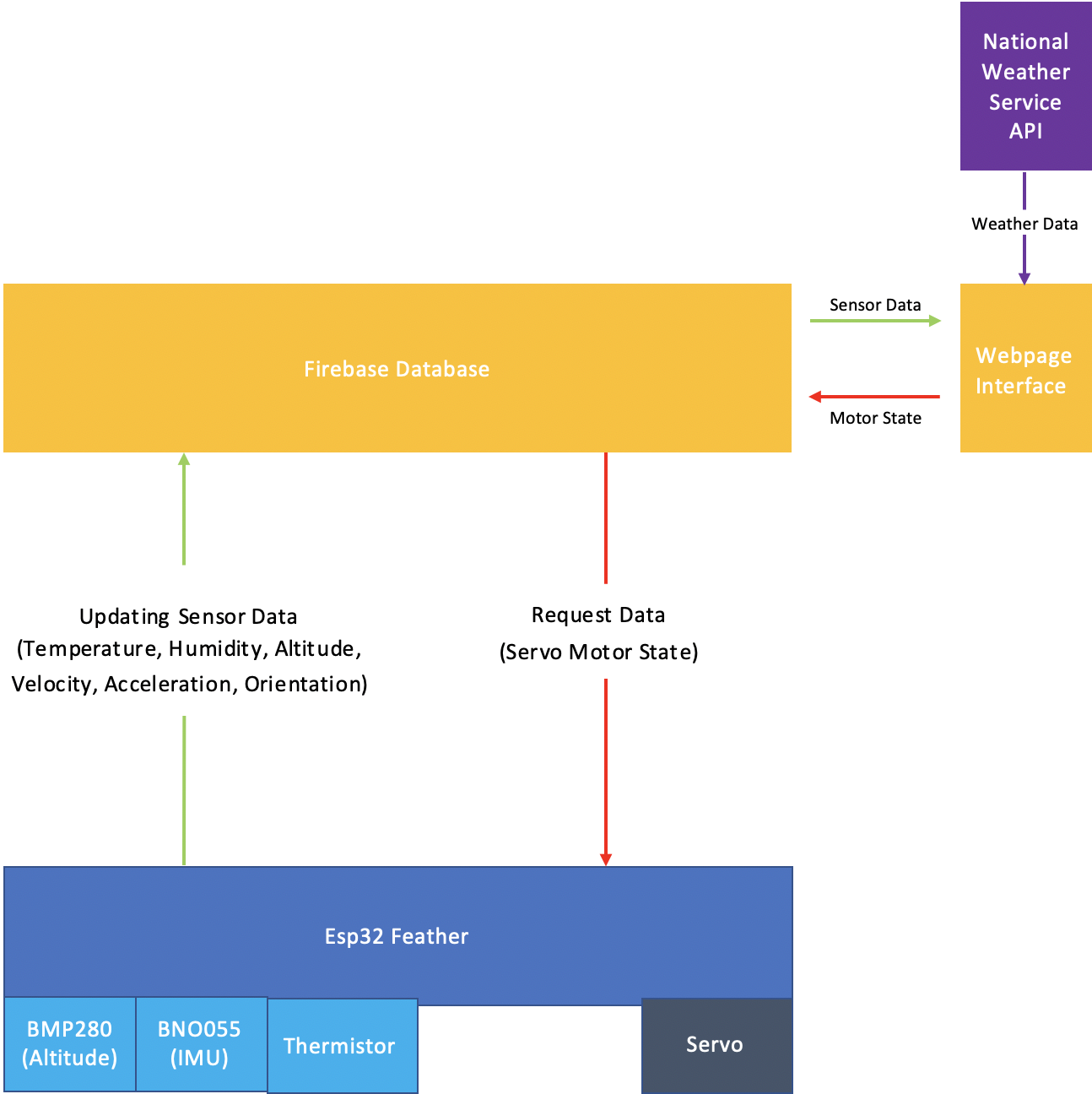
The database collects sensor data (IMU, Thermistor, Pressure Sensor) from the ESP32 and displays it on the webpage. The database also collects the angle of the servo motor from a html form on the webpage, and it sends that data to the esp32. Below is the structure of the network.
7/29
I needed to build the electronics of the hot air balloon before I start testing. The components I'm using are:
I decided to solder everything onto a proto board for better organization and structural integrity.
Learning how to Solder
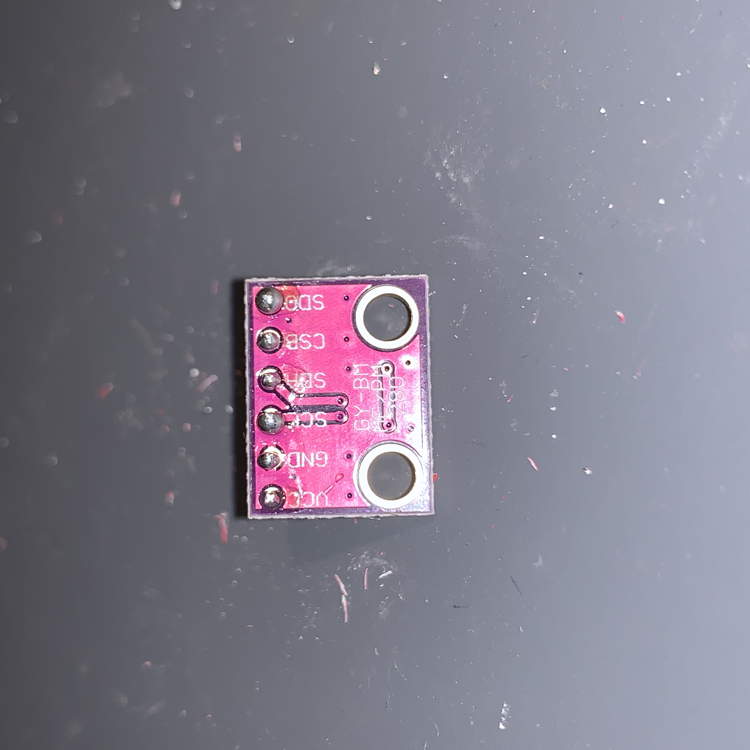
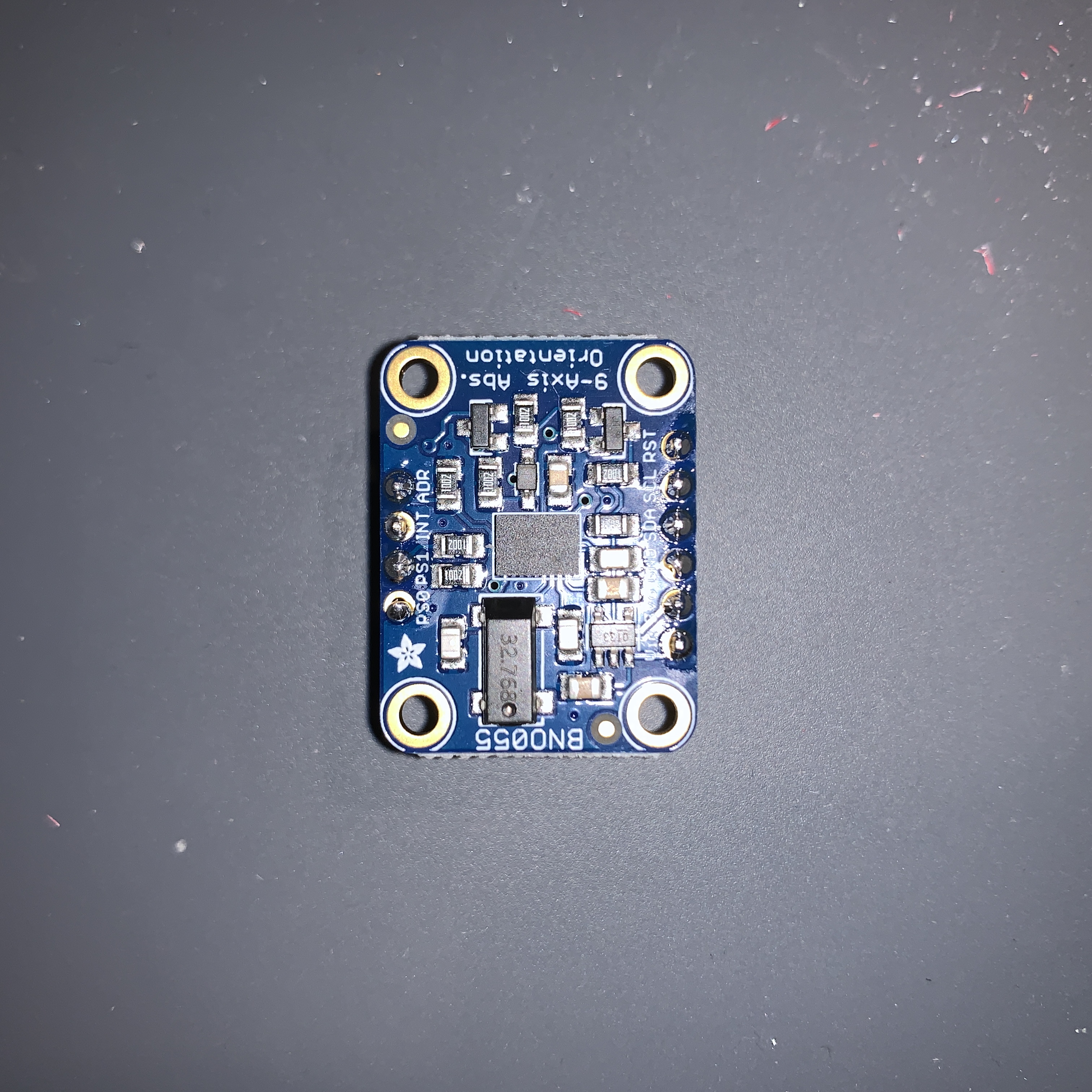
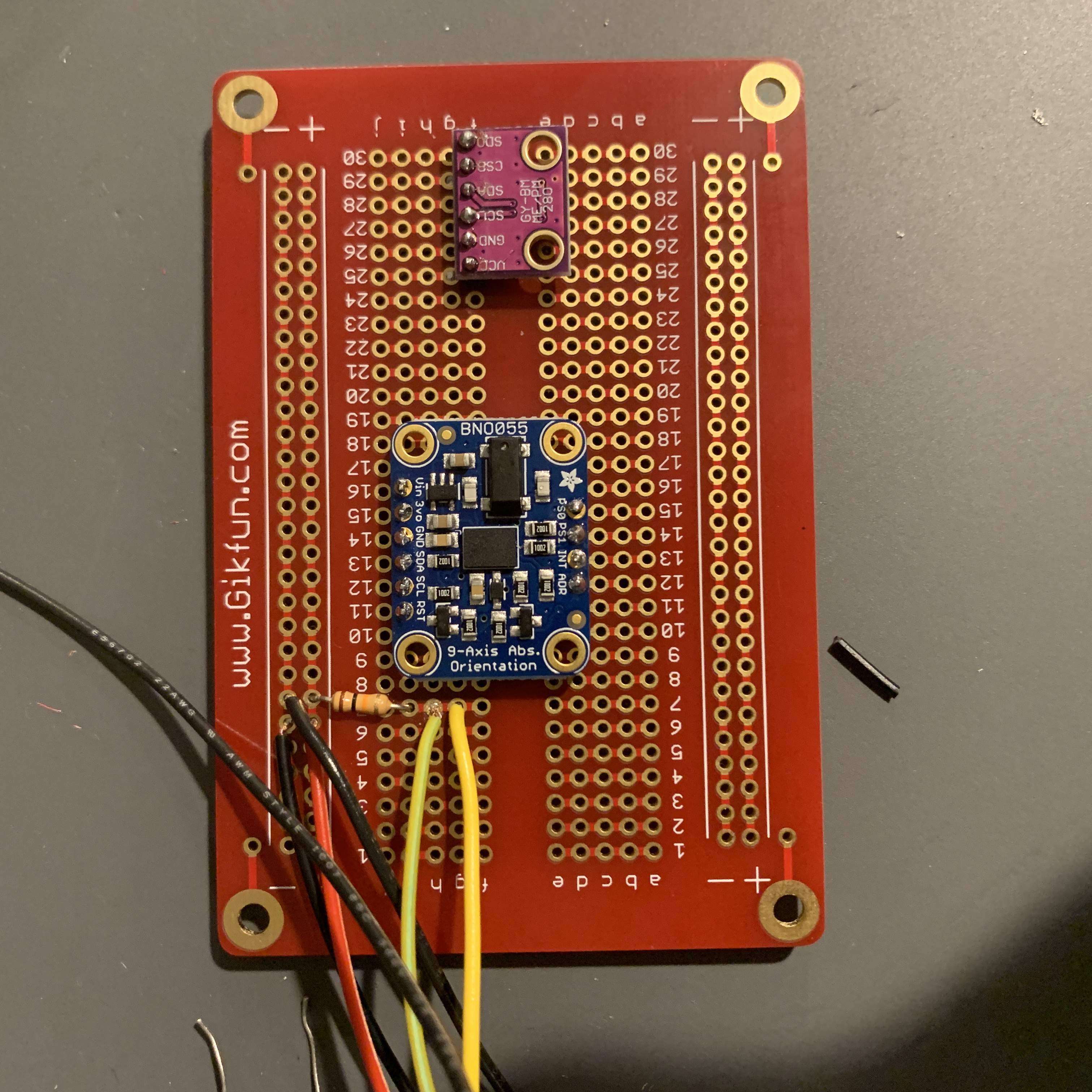
I went to my friend Daniel's house where he had a soldering station. I have never soldered before, but with some much appreciated help from Daniel, I got started. First I needed to solder header pins onto the BNO055 and the BMP280. Here is my first attempt at soldering:
It doesn't look great. I was scared of the heat of the soldering pen, and it was awkward to get solder to stick onto the pins. I had more of the BMP280, so I soldered multiple times until I made one I was happy with. I still wasn't great at soldering, but I was a bit better.
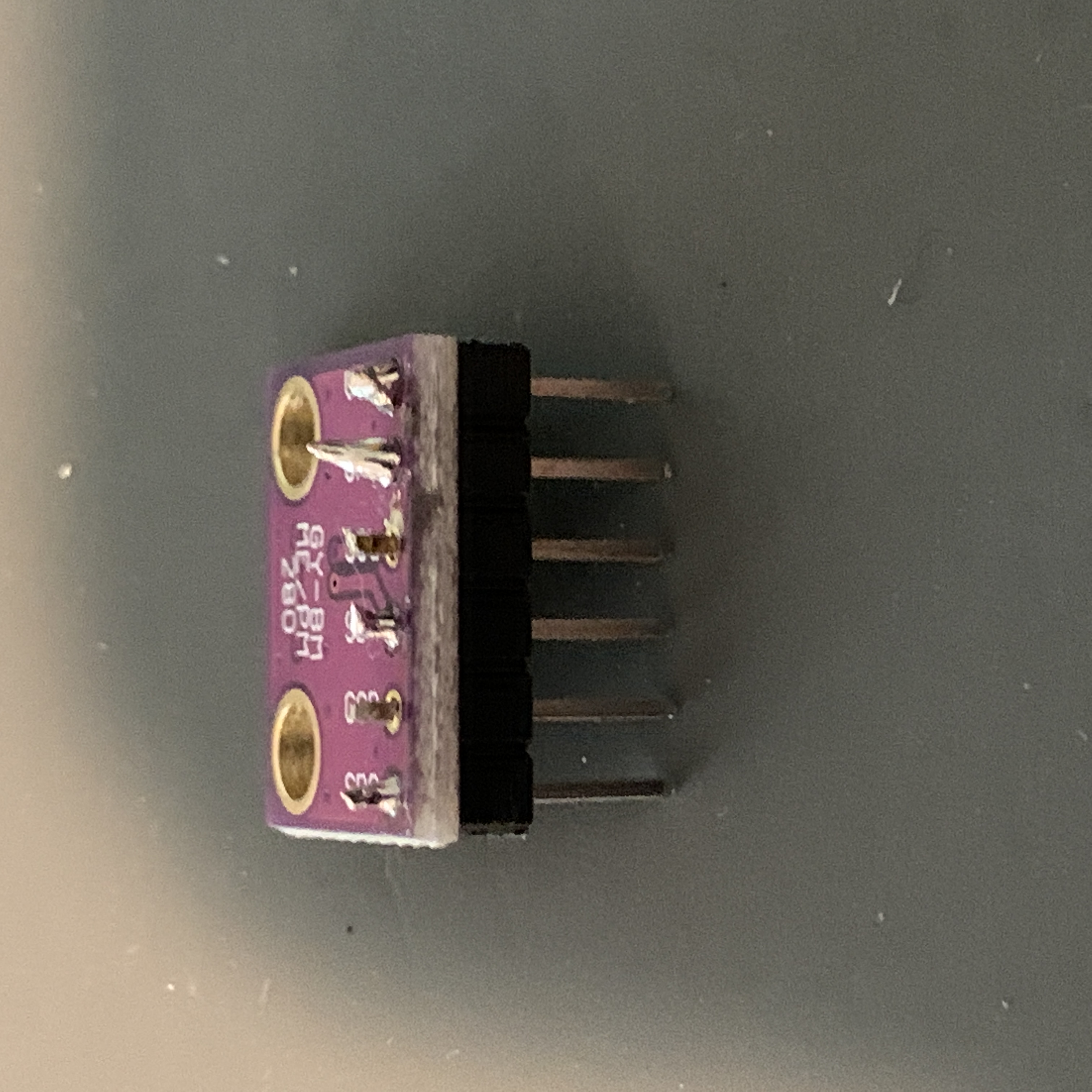
Sensors
I felt ready to start soldering for real, and so I started with my sensors.
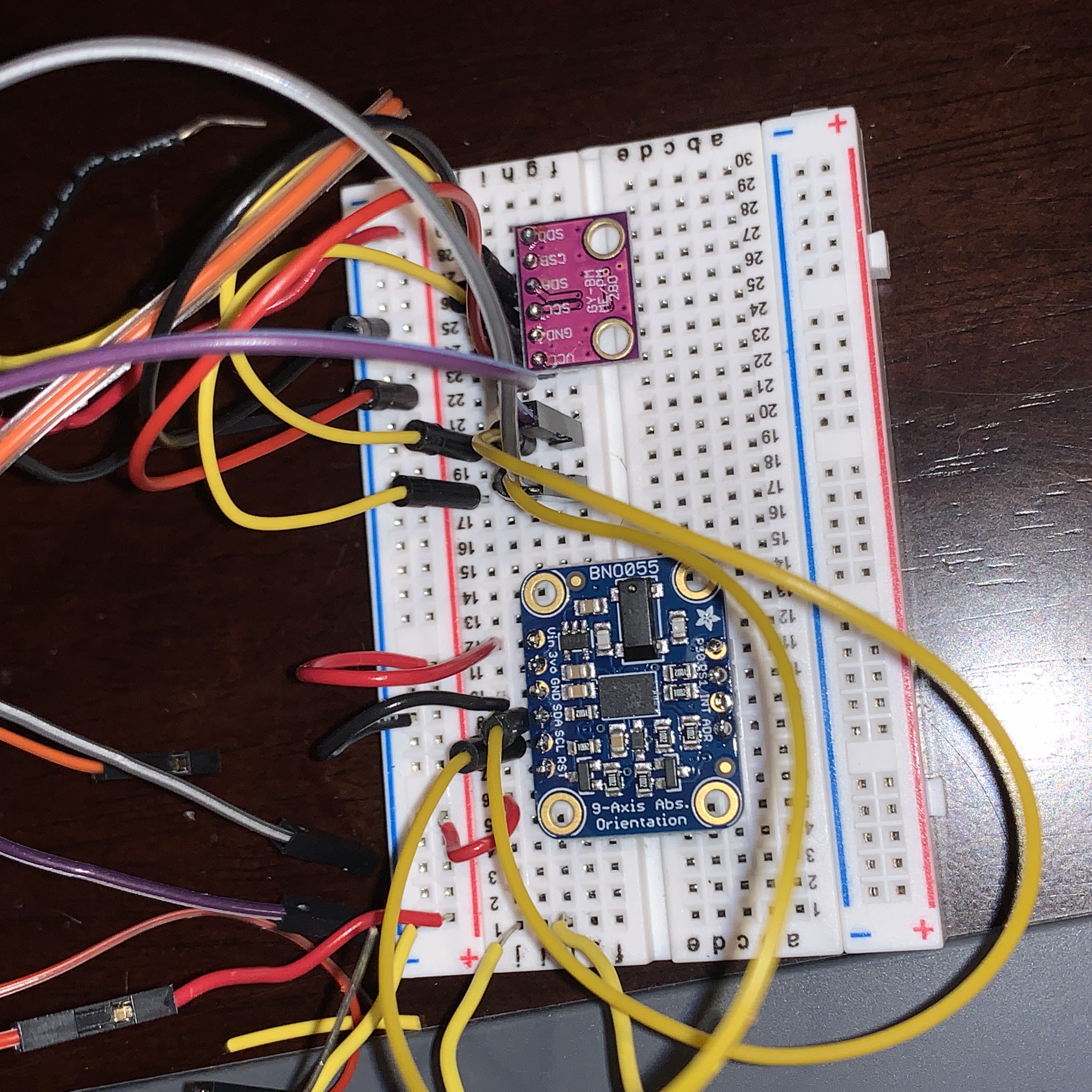
Breadboard and Circuit
Now I needed to build circuits for these sensors on a breadboard before transferring them to a protoboard. It was fairly easy to setup as I followed the adafruit tutorials about the and the BNO055.
I tested these circuits while they're still not permanently attached. I quickly found out that the Adafruit libraries are very poorly documented. Since I was using I2C connections, I needed to specify the addresses for each board (0x28 for BNO055, 0x76 for BMP280). The problem was that I didn't know how to, and I had to resort to going into the source code on github to figure out which function allowed me to put in addresses.
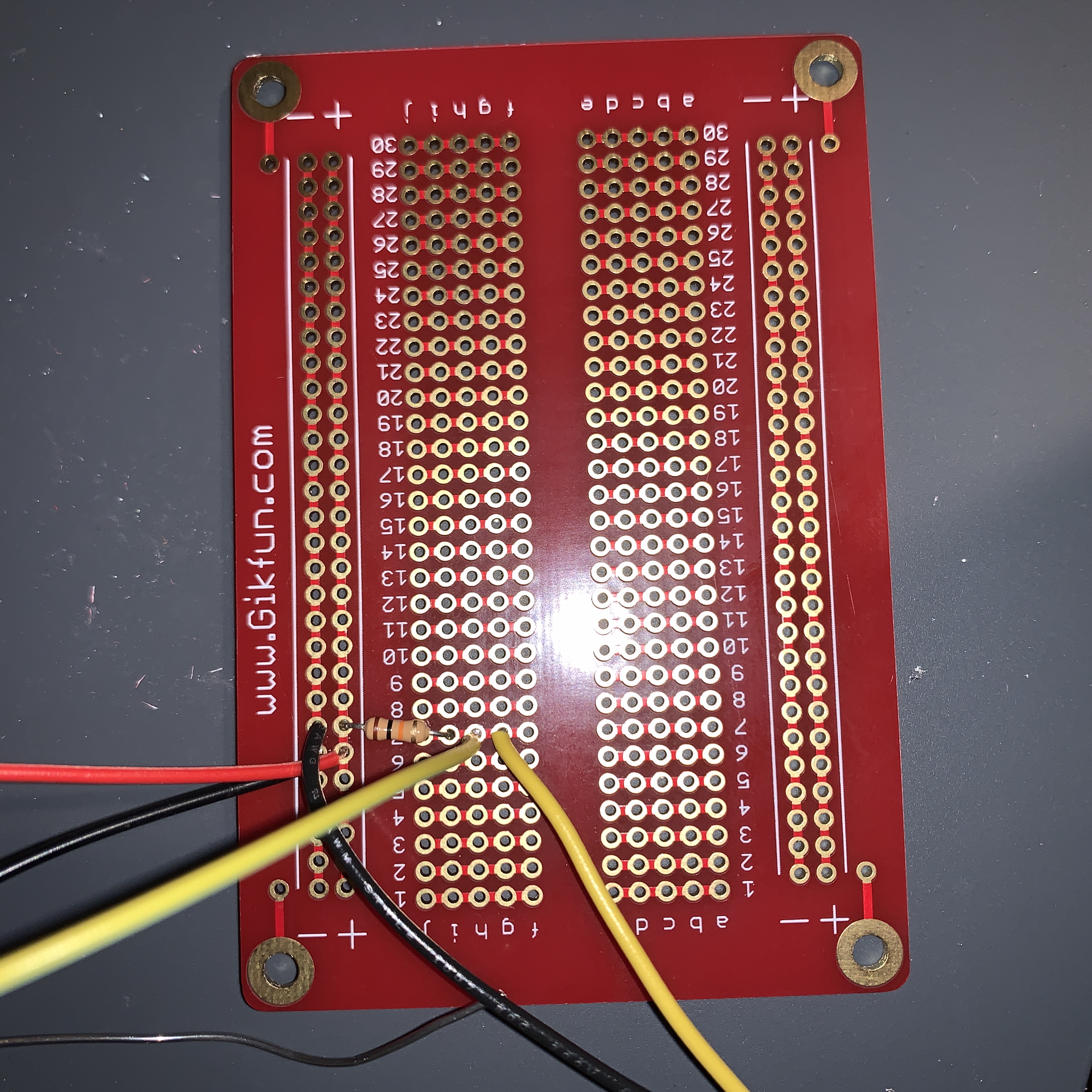
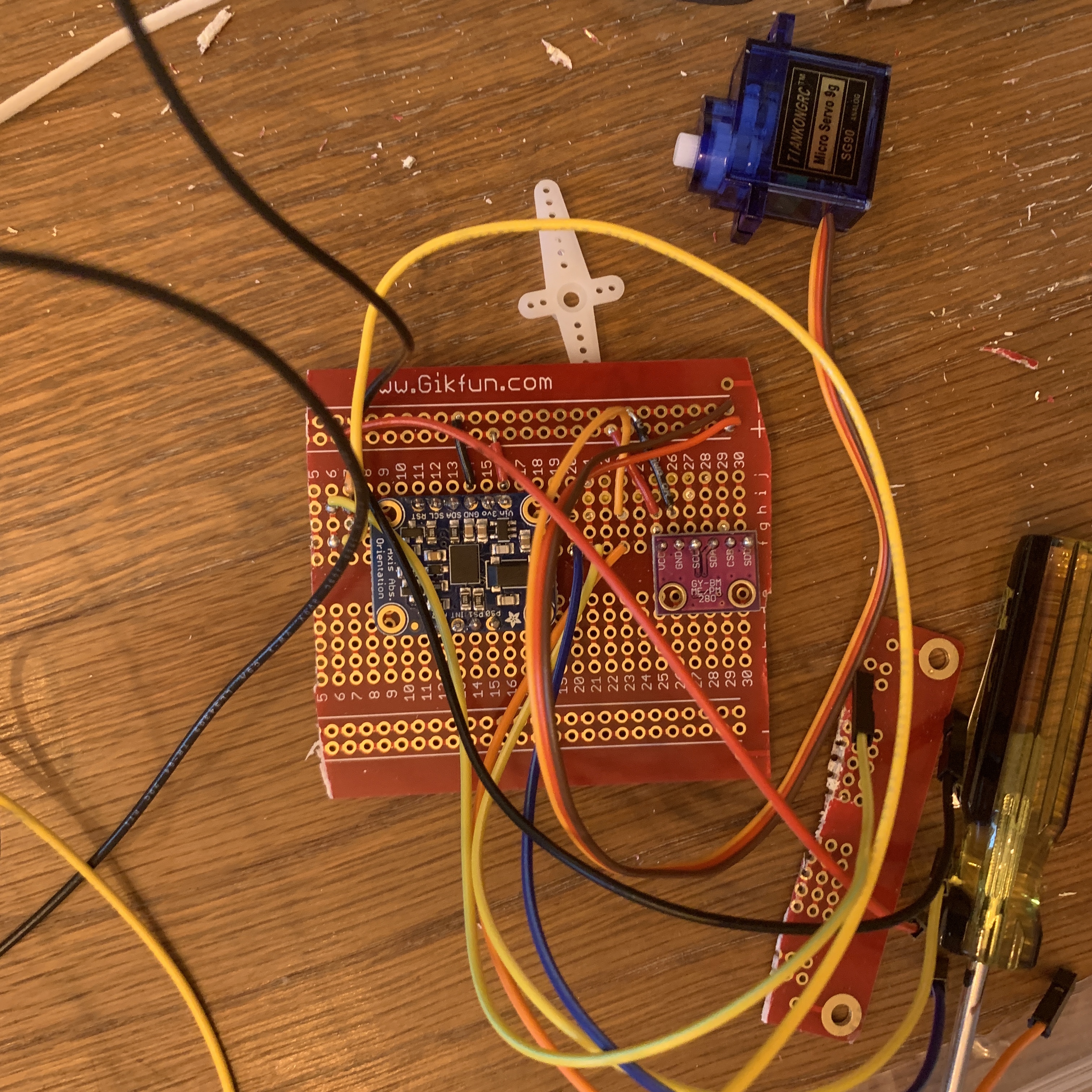
Protoboard
Now it's time to get out the proto board. The board is larger than my 70 x 70 mm basket, but I can always cut the boad after soldering. I would leave female headers hanging lose off the proto board so that I can connect my esp32 feather at any time.
First, I put on the thermistor. It is soldered to the two yellow wires going off the picture. They're each around three feet, which will allow me to tape the thermistor at the top of the envelope.
Next, I soldered on the two sensor boards.
At this point, I felt pretty comfortable with soldering. I learned through experience that I needed to let a small amount of liquid iron sit on the soldering pen, and then let that drip onto the board and fill up the hole by itself.
Finally, I separated the three wires of the servo motor and connected them to the protoboard. I seem to have lost the frontside picture of this stage, so I put below a picture of the board after it's been cut. The circuits are still the exact same.
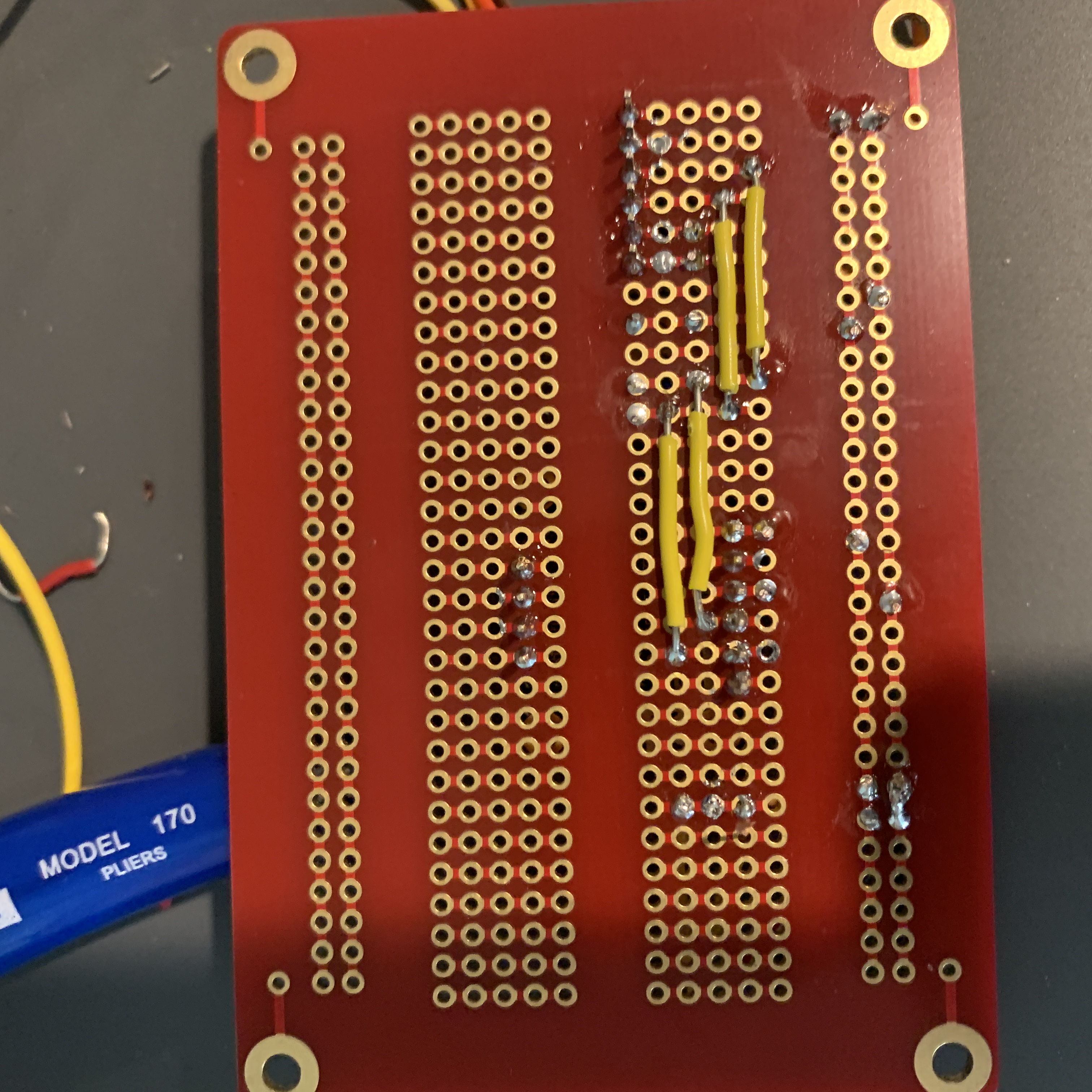
Mistakes
Unfortunately, as I was about to test, one of the data lines going to the esp32 broke, and I was left with a stump of iron. My solution was to go around the broken stump and build my own an electrical connection, which is the white line below.

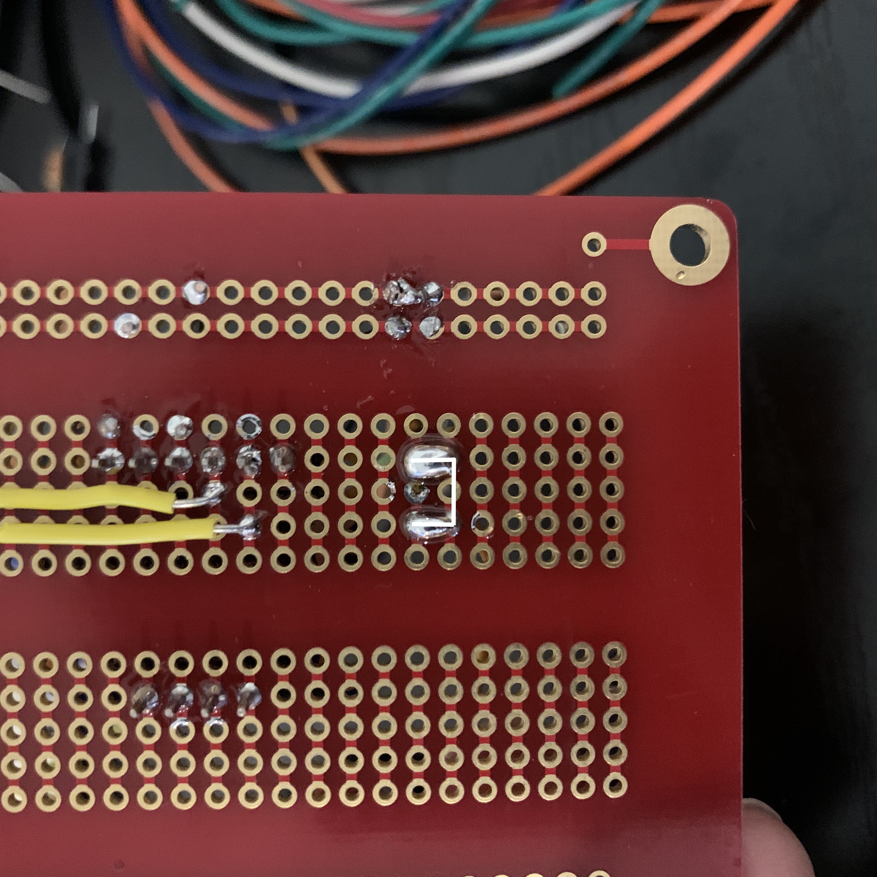
I used a crude temporary code to test my circuit, and it worked! The next step is to build the basket and the envelope of the hot air balloon so I can start testing. The sensor data can come later.
Edit (8/6): I'd like to point out that the stripped wires I attached straight to the protoboard was very prone to snapping off. In the future, I will always use jumper wires or header pins that aren't as fragile.
7/31
It turns out that the gorilla tape I was going to use on the envelope has a delayed delivery, so I just built my basket today. Here's a reminder of what my basket is.
I used Titebond III: a waterproof wood glue. It's important to apply glue to both pieces before sticking them together because the glue needs to spread into the wood pores. After gluing, I clamped them down with rubber bands and let the glue set for 24 hours.
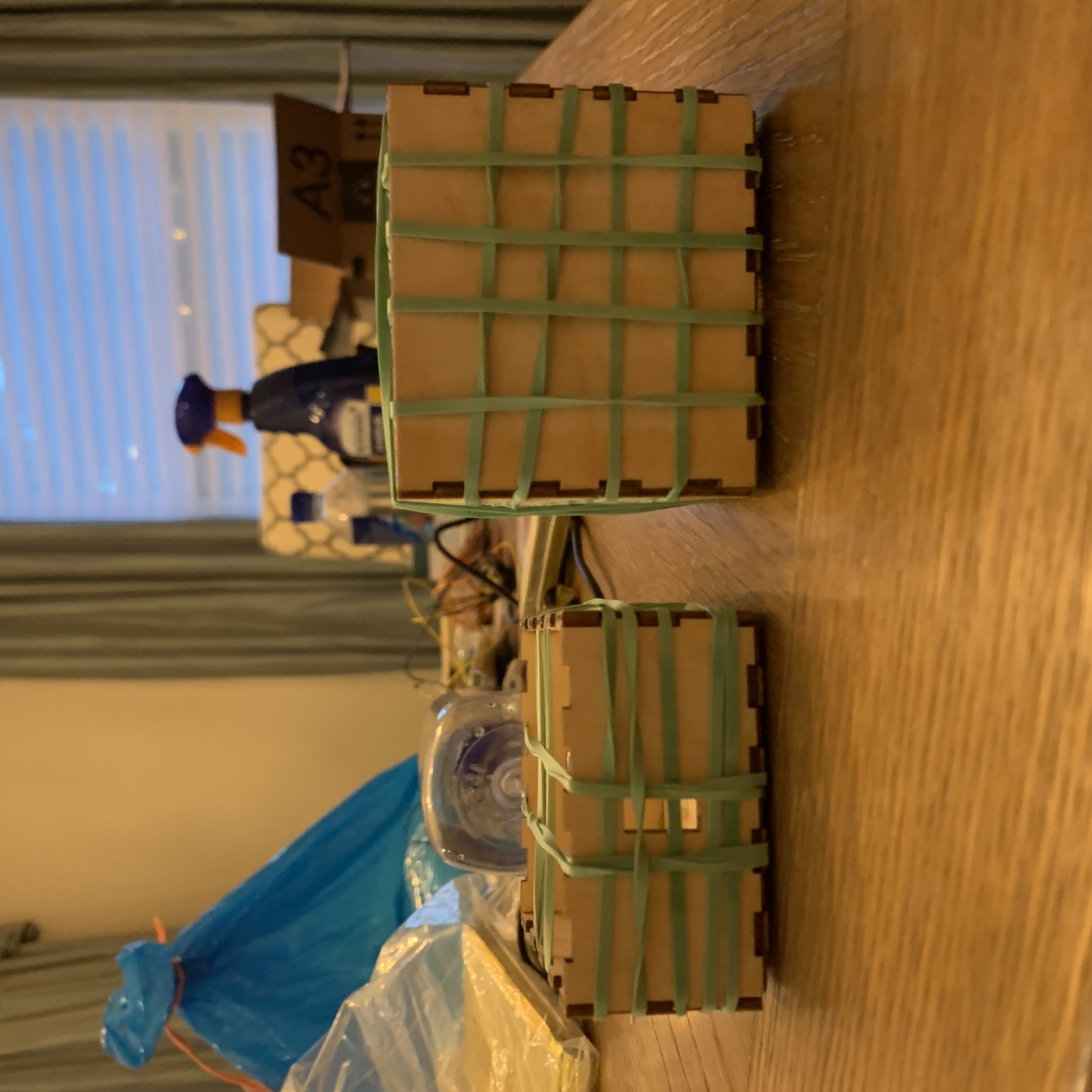
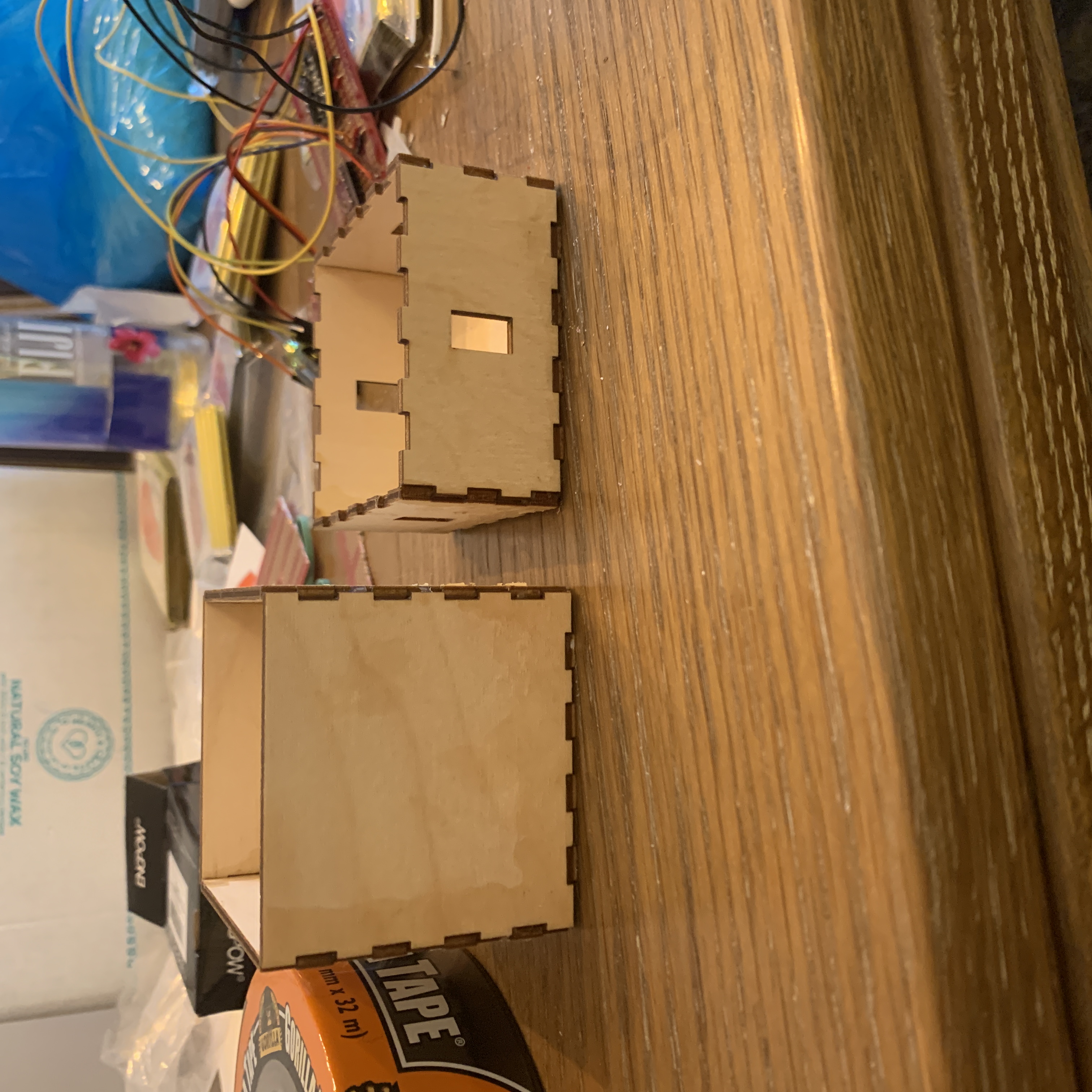
They press-fit together into a single box. I opted out of gluing them together so I can freely move electronics in and out of the smaller box.
8/1
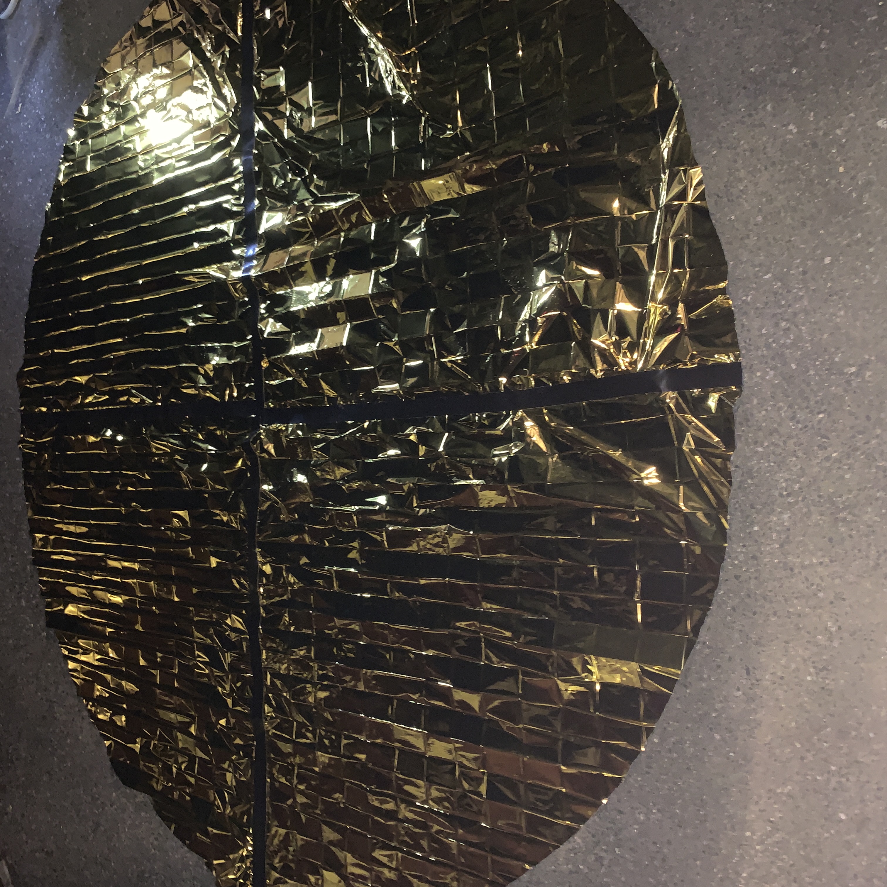
I first tried to build the envelope according to my previous calculations; however, I quickly found it to be too big for my backyard. It also would have been too hard to neatly organize that huge of an envelope.
Instead, I brought down the diameter of the circle cutout to just 3 meters (instead of 4.8), and this still could have lifted my balloon only with less leeway for extra weight. I taped together several mylar blankets and cut out the shape I wanted.
Prototype #1
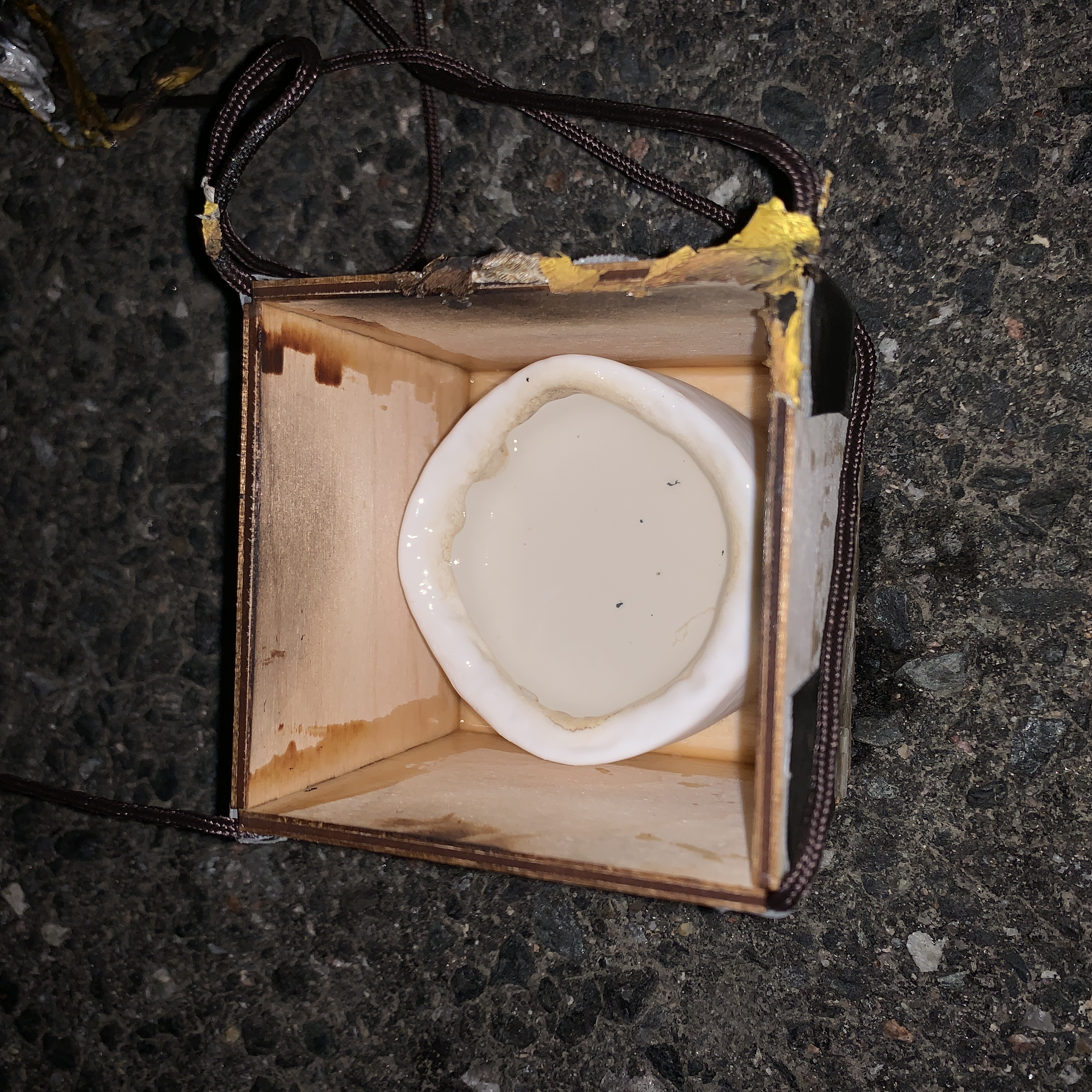
I attached that to my basket via four strings, and got to testing. This didn't go too well. I had used the alcohol I talked about a couple weeks ago (Isopropyl Alcochol), but it was too hot, and it burned my envelope, my 3d printed model, and my lasercut basket.
Additionally, the envelope was still very floppy and hard to control.
Prototype #2
My attempted solutions were:
- Use helium balloons to create buoyancy so that the envelope can be smaller.
- Attach a square bracket to the bottom of the envelope to provide structure.
- Hang the basket with ropes to prevent fire from touching the flammable mylar.
- Replace the wax container with a heat-proof ceramic container, which only weighs 30 more grams.
The helium balloons worked; however, the buoyancy force was still relatively smaller than the balloon's mass, so I needed more balloons to make them almost equal. The envelop was also squished by the balloons, which just means their strings need to be longer. I'll also add hi-float next time so that the balloons can last for longer periods of time.
Before I get to the final test, I needed to calibrate my sensors, build a presentable web interface, and install electronics onto my balloon.
8/3
I wrote some code to read data from the sensors and send them to my firebase database. Here's a reminder of my network structure.
Sensor Problems
The IMU sensor returned the same value for acceleration and orientation, and the BMP280 also reported the same for pressure and humidity. I looked online and found that other people had the same problem. Their conclusion was that there's a flaw in the adafruit sensor library, and sadly, I don't know how to deal with that.
The returned data still represented orientation and pressure, just not acceleration and humidity; therefore, I was still able to get the two most important data I wanted.
Sensor Calibration
I needed to calibrate two things: the Gyroscope and the Altimeter.
According to the Adafruit website, I just needed to let the BNO055 stand still in any position for it to calibrate. There's also a very useful function bno.getCalibration(&system, &gyro, &accel, &mag) that gives gyro a value of 3 when it is fully calibrated.
I needed the current sea level pressure in my area to use the altitude sensor. This is easily done using the national weather service API that I've already used before. I'm accesing this API via javaScript, sending that to the database, and then having my esp32 get that data from the database.
In javaScript, using setInterval() allowed me to repeat this request at specified intervals of time. This is really helpful since I don't want to be constantly bugging APIs for data.
Lastly, I added these data to the web interface. Here is my my website and database code, and once again, here is my esp32 code.
8/4
I wanted to make my web interface look presentable before testing since I wanted a side by side video of my web interface and the balloon flying.
Learning
It was my first time encountering p5.js, but it wasn't as challenging as I thought it would be. Drawing the different shapes came naturally to me, and there were plenty of useful things like mouseX, mouseY, and mouseIsPressed to create interactivity with my mouse.
The web pages that helped the most were interactivity tutorial, the reference page, and the online editor. The online editor was a life saver since it allowed me test my positions and proportions in real time, instead of wasting 10 minutes for my git commit to load onto my Github pages.
Perhaps the most important less I learned was to always use displayWidth and displayHeight for everything. This will make the website adaptable to different browser windows.
Servo Slider
I wanted to make my servo position's slider a half circle. This way, a user can visualize the 180 degrees right on the webpage. To do this, I needed to make a "knob" move around in a circular motion with my mouse.
At first, I let the X position of the knob be the X position of my mouse (with a factor for speed), and I calculated y according to the equation of a circle. This did form a half circle, but the movement of the knob was super clunky. Obviously it doesn't feel very user-friendly when its position solely depends on my mouse's X coordinate.
I realized that I needed to use trig functions to find the angle between the cursor and the center point. Then map that angle to the slider. To do this, I built a coordinate system with its origin at the center of the page. The below image shows how to calculate the angle of my mouse based on its and X and Y coordinates (Imagine the vertex of the triangle to be my mouse).
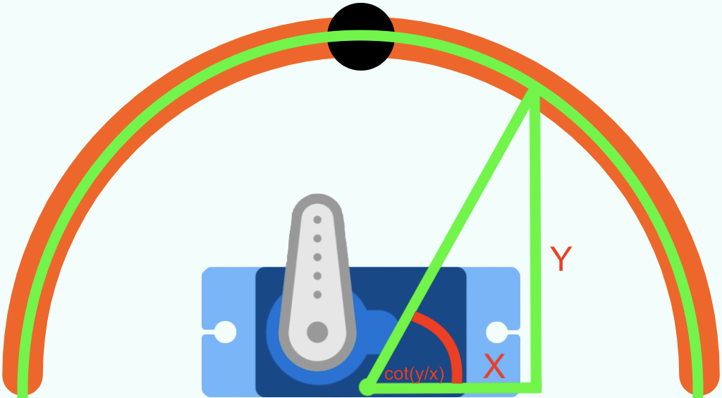
The only problem was that cotangeant only gives back angles ranging from -90 to 90, so I used some if statements to identify each quadrant and correct the angle. Additionally, I told the program to ignore the angle when it was in the third and fourth quadrant.
Knowing the angle and the radius, I can now calculate the X and Y coordinates of the black knob and plot it.
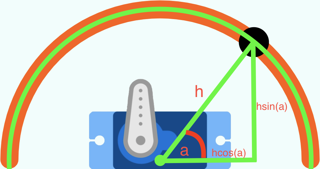
The icing on the cake is that these calculations have already given me the data I needed: the angle of the servo motor.
Sensor Data
The main challenge was building a smoothly sliding dataline.
At first, I had a while loop that kept drawing lines with coordinates approaching the intended data. These coordinates would get closer and closer to the actual data by a given rate of change. However, I realized that since everything was happening in a while loop, the background wasn't being refreshed, so the lines were just overshadowing each other.
Next, I got rid of the while loop and just let the draw() function act as the loop. This way, the background refreshed every iteration of the loop, and I was able to see movement.
Here's the code I used.
However, now I have to put in another data line. Since I didn't want to cluster my code with copy and paste, so I opted to create a dataLine class instead. It was pretty simple. The only annoying thing I found was that I need to put the this keyword in front of every single object instance variable.
Next, I added in time, orientation, and the national weather service API using the text() function. The frameCount asset allowed me to do asynchronous timing so that I'm not sending a request every frame. One weird thing that wasted a bit of my time was that frameCount is set at 1 during the first iteration of the draw() loop. I had written my program expecting it to be at 0.
To finish up, I tidied my code and removed the extra html elements from the first iteration of my interface. However, there was one last problem. My once function suddenly stopped working despite me not changing anything. The code is very standard:
function getTemperature() {
  var tempRef = firebase.database().ref("Sensors/Temperature/Data");
  var temp;
  tempRef.once('value', function(tempDataSnapshot) {
        temp = tempDataSnapshot.val();
  });
  return temp;
}
After debugging, it seems that tempDataSnapshot actually holds the correct value, but for some reason it is not passing that on to temp.
I switched to on(), and it worked. However, since this function will be called repeatedly within the main loop of my p5.js, using on() would initiate an infinite amount of listeners. Once() would only make one query before closing itself.
In the end, I simply got rid of the functions and integrated once() straight into my draw() function.
Here is the code for the final version of my interface. You can also see it for yourself right here, although the data probably won't be working since my esp32 is turned off most of the time.
8/5
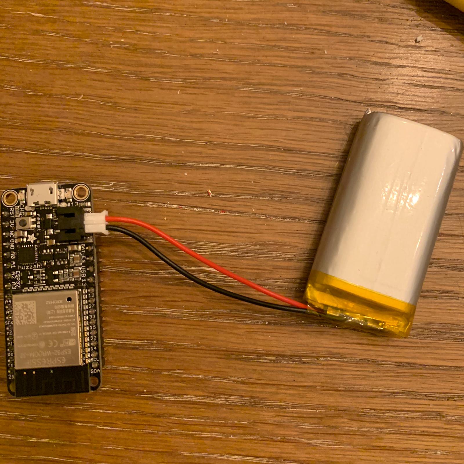
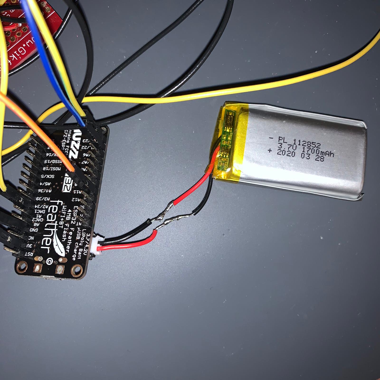
Lipo Battery
First I had to fix the Lipo batteries, which I've been fighting with for the past 2 weeks now. Fortunately, page 21 of this pdf told me that the esp32 JST connector's polarity might not match the polarity of lipo batteries I find online. To switch the polarity, I the wires of the lipo battery apart and soldered them together again. It worked!
Servo Motor
Next I screwed the Servo motor on to the 3d printed mount. I had forgotten to consider the wires back then, so I had to attach the motor on the opposite side of what I had intended it to be on.
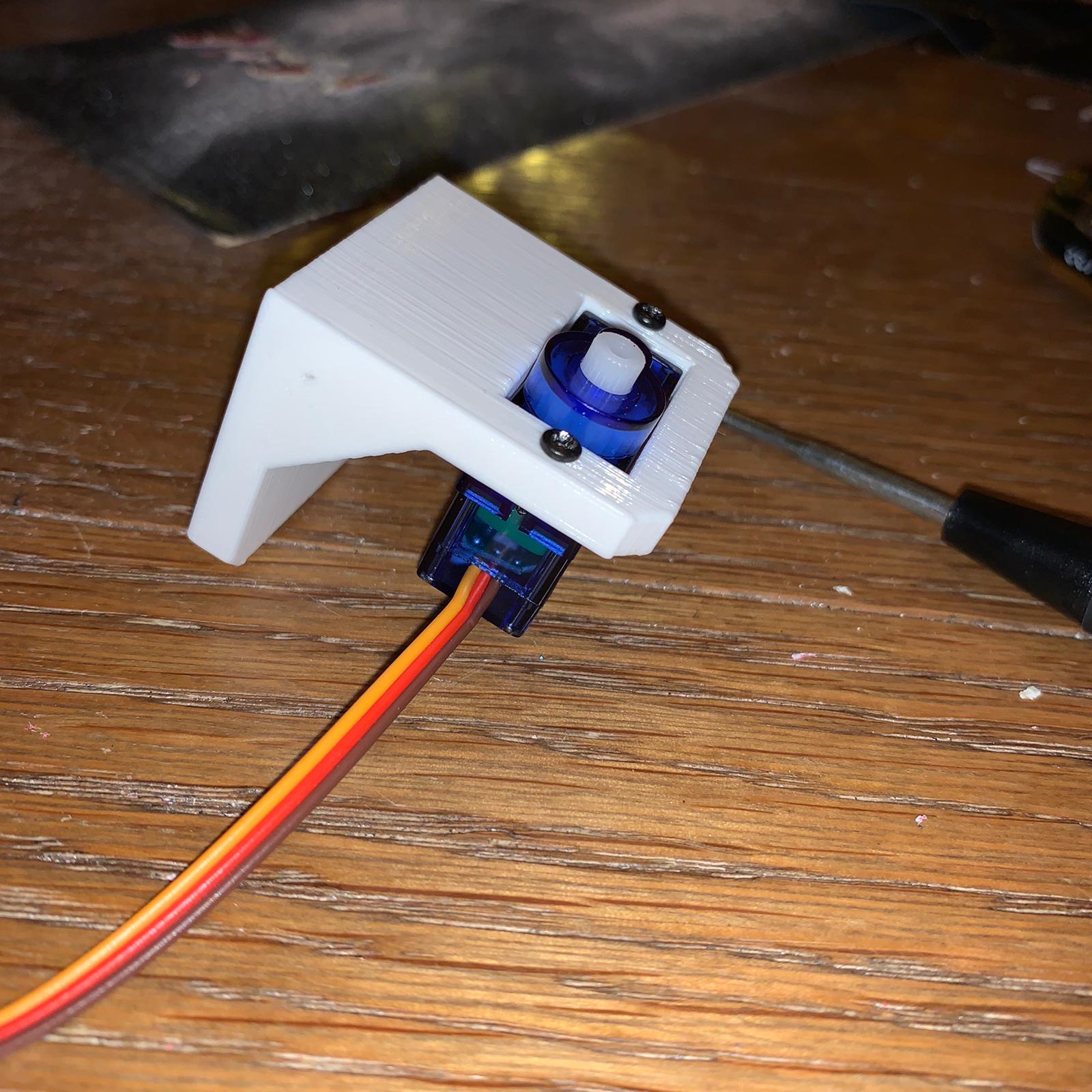
I attached a few paper clips to the motor's horn and stuck a piece of aluminum foil on top of the paperclips. This aluminum foil would cover the fuel container and stop the fire. I used hot glue to secure everything.
Putting it all together
The only inconvenience was that I had to cut open and resolder the motor wires so that my servo could connect to my esp32 through the tiny opening in my basket.
I also tried my best to distribute weight evenly inside my basket. I put the lipo battery and esp32 on one side and the motor on the other. Here's a short demonstration of my electronics after I assembeled everything:
8/6
Finally, it's all going to come together, and … it kind of worked. Please go here to see the results.